2
\$\begingroup\$

Hi so I've just bought a 60's tube guitar amp from the U.S, I live in Australia. Through searches across the internet I've found a few potential issues with the safety of running the amp through a 240-110v step down transformer.

Firstly, the amp has no power transformer, it rectifies the line voltage directly. A common safety modification is to add an isolation transformer, I figured I could avoid doing this by using an isolated step down transformer

Secondly, the amp isn't grounded so if a certain capacitor inside the amp fails, the chassis of the amp becomes live. The standard fix is to add a 3 prong plug and ground the chassis, but I've read that the ground plug in isolation transformers dont actually ground.

Thirdly, would the 50hz of Australian mains damage the output transformer or any other component of the amp, designed for 60hz?

Thanks in advance

Here is the schematic for the amp

http://www.magnatoneamps.com/schematics/magnatone_401_412.pdf

\$\endgroup\$
3
  • 1
    \$\begingroup\$ Wow that's such a dangerous design! \$\endgroup\$
    – Andy aka
    Commented Nov 8, 2016 at 10:26
  • 1
    \$\begingroup\$ Looks ok to me with transformer isolation on guitar input. If 50Hz ripple hum is poor at high output, increase 50uF value as this is chosen for 60Hz e.g. add a bit more.. if noticeable hum. DC, T=5k6*50uF=280ms >>280/20ms=14 =~8 % ripple voltage at max load. try 100uF and then consider silicon diode instead of rectifier if there is hum \$\endgroup\$
    – D.A.S.
    Commented Nov 8, 2016 at 13:11
  • 1
    \$\begingroup\$ Fender changed to solid-state rectification in many of its Professional Series amplifiers in 1960 ... higher efficiency and power as well a bit but use good quality caps \$\endgroup\$
    – D.A.S.
    Commented Nov 8, 2016 at 13:33

4 Answers 4

1
\$\begingroup\$

Since the amplifier is mains connected you can use an ordinary step down transformer. An isolated stepdown is nice but not needed. The extra safety introduced helps to prevent electrical hazard in case the input or output transformer of the amplifier fails.

If all is good then the common return from the amplifier is not connected to the chassis. The chassis itself can therefore be connected to earth in both situations. Without isolation transformer or standard stepdown transformer.

Finally there is no problem in connecting the amplifier to 50 in stead of 60 Hz mains.

Warning. If you are working on mains operated equipment be careful and respect the fact that a mains voltage can kill.

\$\endgroup\$
1
\$\begingroup\$

All you need is a step down transformer. See the note next to the power plug at lower right. It specifically says that it's designed to work with 50 or 60 Hz power.

However, my preference would be to replace the whole power supply in the lower right corner with a off the shelf modern DC supply, if you can find something that puts out 130 V or can be adjusted to that. That takes care of isolation, the rectifier tube wearing out, and the inevitable hum this amp has on the output.

But, it's not quite that simple. You then have to find a way to run the two fillaments and the indicator lamp. It seems the filaments are 45 and 20 V, for a total of 65 V in series. That doesn't quite add up with the 200 Ω resistor dropping 20 V due to 100 mA thru it. That only comes out to 95 V instead of the expected 110 V. This is probably due to filaments being rather forgiving in voltage. With 110 V applied to the resistor and filaments string instead of 95 V, the filaments get a little hotter than nominal, but probably not decrease tube life significantly. Another possibility is that the filaments don't really both want to run at 100 mA. Putting two dissimilar filaments in series is rather a hack. This was done to not need a large and expensive power transformer. Perhaps the somewhat higher than stated voltage is due to one of the filaments just getting the minimum at that voltage.

One option with a 130 V DC supply is to just increase the 200 Ω 5 W resistor to get the indicated 100 mA thru the filaments, or the intended 65 V across them. Again, check that each filament gets at least its minimum voltage. A more modern option is to make a small buck converter that reduces the 130 V to 65 V to run the filaments from. You can still be retro and waste a lot of power by running a LED from that with a suitable series resistor. That LED replaces the neon bulb.

\$\endgroup\$
2
  • \$\begingroup\$ "Putting two dissimilar filaments in series is rather a hack." Not necessarily. There are tubes that are designed for a specific heating current instead of a specific heating voltage. In Europe, tubes starting with E were meant for 6.3V heating, while tube starting with P were meant for constant current heating (I don't remember the current, might in fact be 100mA). Putting different P-series tube filaments in series was proper design. \$\endgroup\$ Commented Nov 9, 2016 at 0:19
  • \$\begingroup\$ @Michael Karcher .I remember U type valves being lower current for series string filaments on radios and the P type valves being higher current for TV. \$\endgroup\$
    – Autistic
    Commented Feb 17, 2017 at 11:31
0
\$\begingroup\$

The amp is designed to run on DC, that's why it rectifies and smooths the AC input.

You may want to consider increasing the size of the smoothing capacitor to accommodate the 'lower' frequency. It does state 50/60Hz operation but its only half wave rectified and at 50uF that could be quite 'hummy'. For old equipment its common to replace the old electrolytic caps anyway.

You don't need an isolation transformer because the 240/110 transformer performs that function as well.

A good (direct) ground connection to the metal chassis is highly recommended.

\$\endgroup\$
0
\$\begingroup\$

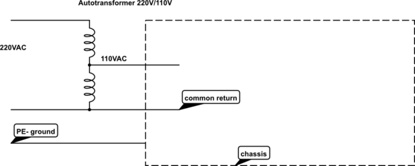
For the galvanic insulation of the input signal there is T2, for galvanic isolation of the output of the amp there is a T1. You don't actualy need a third transformer for the galvanic isolation from mains. You can use a autotransformer, which is smaller and chaper but it doesn't provide a galvanic isolation. The chassis has to be grounded with third wire, ground wire.
The 50/60hz difference would not give any problem effect. As you might see, the amp works on AC or DC voltage, there is a tube that is a half wave rectifier/regulator.

schematic

simulate this circuit – Schematic created using CircuitLab

\$\endgroup\$

Your Answer

By clicking “Post Your Answer”, you agree to our terms of service and acknowledge you have read our privacy policy.

Not the answer you're looking for? Browse other questions tagged or ask your own question.