0
\$\begingroup\$

I need to build an active crossover circuit for my 2-way speaker design. I decided to use TDA2009 as my audio amplifier. TDA2009 is shown connected below in the picture. My question is: how can I modify the TDA2009 circuit to implement the circuit in the gray box?

I know that C10 and C11 are need for the DC battery to minimize noise as well as C1 and C2 (2.2uF). So these 4 capacitors need to stay in the circuit. What about C4 and C5 do I need them? or I just connect the high pass filter of the gray box directly to pin 8 and 4 of TDA2009 and the low pass filter directly to pin 10 and 2 of TDA2009? What do you think?

Finally I need it to be active filter that is my TDA2009 need to be placed after the filtering circuit (gray box).

Please I need your help concerning this. I came to this forum after weeks of research because I am really stuck.

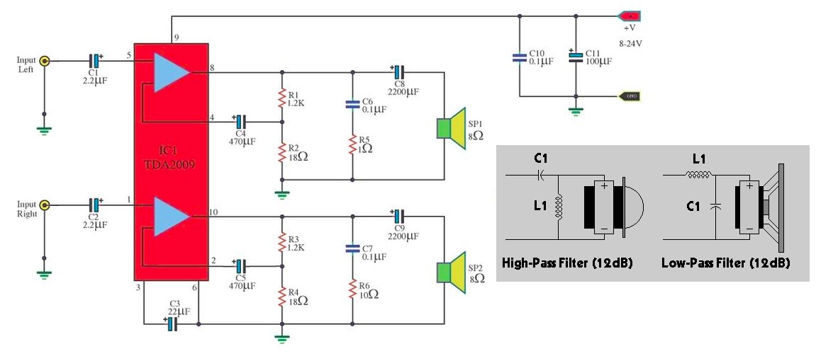
Thank you for your help in advance :) enter image description here

\$\endgroup\$

3 Answers 3

2
\$\begingroup\$

If you don't already have it you can download the TDA2009 data sheet here Datasheet.

The input to the amplifier is not a differential amp. So you need C4 and C5 to prevent changing the internal bias. If you look at figure 12 in the linked data sheet you will see that putting 12kOhms to ground on the pins 2 and 4 will cut the amp off. That is why C4 and C5 are needed.

The data sheet already provides a circuit for doing an active crossover before the amp. it is shown in figure 15.

\$\endgroup\$
0
1
\$\begingroup\$

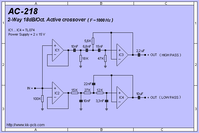
The trouble with the "gray box" is that it gives no indication of what the cut-off frequencies are and, the filtering is dependant on the speaker as load so, I would not recommend trying to model this but, instead, use op-amps.

There are plenty of op-amp active filters on-line such as this one: -

enter image description here
(source: kk-pcb.com)

The op-amps need to be "powered" appropriately of course. I recommend using a split rail supply to ensure lowest noise but you can make it single supply powered with a little care; for instance, in the circuit above you would need to provide a mid-rail supply (probably from another op-amp) and the 18k, 100k and 47k resistors would connect to this AND you would need to use an input coupling capacitor such as 1 uF where it shows IN+.

You can also combine IC1 and IC2 into the same op-amp - one op-amp can drive the high-pass and low-pass filter quite adequately and the result is that you should be able to use a single quad op-amp package. The outputs shown in the picture above feed into the TDA2009 power amplifier as shown in the question.

The one above has a cross-over frequency of 1 kHz but there are many more here.

\$\endgroup\$
1
  • \$\begingroup\$ Comments are not for extended discussion; this conversation has been moved to chat. \$\endgroup\$
    – Dave Tweed
    Commented Nov 20, 2016 at 12:47
0
\$\begingroup\$

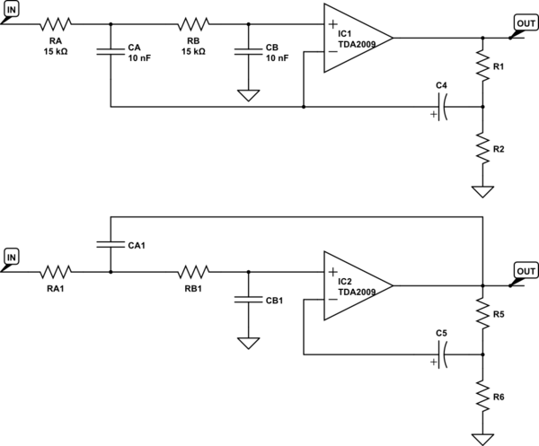
A Linkwitz-Riley seems to be nothing more than overdamped second order filter with Q=0.5. You could try to use TDA2009 itself as an active element for a Sallen-Key cell.

Given the very low resistance feed-back network R1/R2 you could just try to tap a "low impedance" copy of input signal at junction R1/R2/C4.

Now since SK has Q=0.5 if C1/C2=1 and R1/R2=1 you just get to this top schematic for 1kHz crossover.

As you see 18ohm R2 is by far lower then 10kohm+ filter resistors, hopefully this should keep us on the safe side. Running a simulation could make it clear if a good model could be found for TDA2009.

schematic

simulate this circuit – Schematic created using CircuitLab

A second chance would be to use full output as feed back source, just like second schematic above. In this case filter values should be calculated for desired Q including TDA2009 voltage gain Av=1+R1/R2. In this case given 65+ gain I an afraid we could get a higher sensitivity to parts tolerances or could make it more instabilty-prone, but it's just guessing, we could get sure by doing the math only.

\$\endgroup\$
3
  • \$\begingroup\$ what are the values of RA1 CA1 RB1? \$\endgroup\$
    – Ali Ammar
    Commented Nov 19, 2016 at 13:18
  • \$\begingroup\$ Need to find circuit transfer function and do the math, I have no time right now, if you can't do yourself I can update the post later. Otherwise try first circuit first. \$\endgroup\$
    – carloc
    Commented Nov 19, 2016 at 13:27
  • 1
    \$\begingroup\$ please correct ur answer. It is "Q=0.5 if C1/C2=1 and R1/R2=1" \$\endgroup\$
    – Ali Ammar
    Commented Nov 19, 2016 at 13:30

Your Answer

By clicking “Post Your Answer”, you agree to our terms of service and acknowledge you have read our privacy policy.

Not the answer you're looking for? Browse other questions tagged or ask your own question.