1
\$\begingroup\$

Trying to create a switch-over with two p-channel MOSFETS using arduino. I need to switch between 2 sources with a GPIO pin from my arduino. I've looked into ideal diodes such as the LTC4414 and the LTC4415 but its hard to get them with my local supplier and I want to see if this is possible using FETs. I've seen some solutions using just diodes but I am not really interested in the inefficency they introduce.

The purpose is to do a power switchover e.g. source 1 dies, source 2 switches on.

Source 1: 11.4v, 1300mah nimh

Source 2: 12 DC wall adapter

The circuit it powers will sometimes require somwhere between 2-4 amps peak.

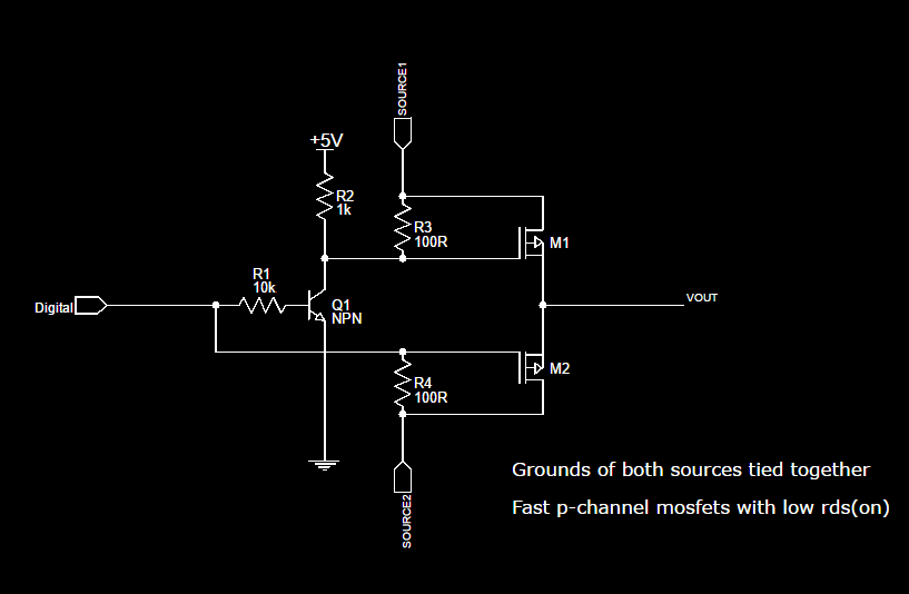
Would the following circuit work?? I don't have any p-channel mosfets to test it out (side note: recommendations welcome). I'm trying to keep everything through-hole (yes I know ... relic of the past) but I don't have the necessary gear to solder small stuff.

enter image description here

\$\endgroup\$
5
  • 2
    \$\begingroup\$ Possible duplicate of What kind of power management circuit do I need to embedded a rechargeable battery in my electronics project? \$\endgroup\$ Commented Nov 27, 2016 at 21:35
  • \$\begingroup\$ i'm looking at your design, but I fail to understand it fully. all it does is switch from wall to batt when wall isnt present. but more components would have to be introduced to make this happen only when given the high/low signal from the MCU? \$\endgroup\$ Commented Nov 27, 2016 at 21:58
  • \$\begingroup\$ Your current circuit has some problems. Let me ask some questions. Do you need IO control of the switchover, or would it be OK to make it so Source 2 is the priority source? In other words, so whenever Source 2 is present, Source 1 will be disconnected? Also, I assume you do not want current to flow into Source 1, right? And you also do not want current to be supplied by Source 1 when Source 2 is present? Because you may need two back-to-back FET's in series with Source 1. Also, maybe you only need a diode on Source 2. Not a FET. Please answer all questions. \$\endgroup\$
    – user57037
    Commented Nov 27, 2016 at 23:45
  • \$\begingroup\$ How much voltage drop is acceptable? \$\endgroup\$ Commented Nov 28, 2016 at 1:21
  • \$\begingroup\$ Note that you're feeding 12V from SOURCE2 into your Arduino via R4, so your circuit will blow up instantly. \$\endgroup\$ Commented Dec 7, 2016 at 15:35

1 Answer 1

2
\$\begingroup\$

In the circuit you show you will not be able to control M1 or M2 since you have not correctly interfaced the gate voltage relative to your input voltages.

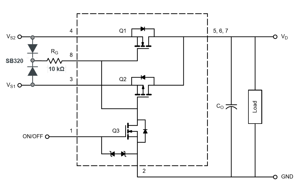
I think what you might be able to copy is the schematic of the Si4700DY (now obsolete but they give a good schematic) http://www.vishay.com/docs/71110/71110.pdf

In this schematic they ideally need VG pulled up to a value equal or greater than either source voltage. In practice you should be able to use two low VF diodes (such as the SB320) and still ensure the FET can be turned off.

You'd end up with something like this:

enter image description here

\$\endgroup\$
3
  • \$\begingroup\$ do you know of a replacement for this particular IC? I havent had much luck finding the new version on Vishay's website and I'm highly interested in this IC or something that operates similarly, instead with a lower voltage of 7.2. as a side note. won't there be a time, albeit small, in which VS2 and VS1 both supply Vd? \$\endgroup\$
    – Alex
    Commented Nov 28, 2016 at 0:59
  • \$\begingroup\$ @Alex. No, it's a break before make switch, and the intrinsic diodes prevent any feedback from one supply to the other. And I don't know of a replacement for this IC. \$\endgroup\$ Commented Nov 28, 2016 at 1:08
  • \$\begingroup\$ Ah makes sense, the reason for the cap \$\endgroup\$
    – Alex
    Commented Nov 28, 2016 at 1:10

Your Answer

By clicking “Post Your Answer”, you agree to our terms of service and acknowledge you have read our privacy policy.

Not the answer you're looking for? Browse other questions tagged or ask your own question.