2
\$\begingroup\$

I'm currently working driving two motors using some sort of PWM or switching such that they run at constant speed, regardless of load. I want to control this entire circuit using one Arduino PWM output pin.I believe that the mosfet I'm using is a logic-level one intended to be driven at 4.5V. The two motors combined shouldn't draw more than 30A stall.

Here's what I have so far:
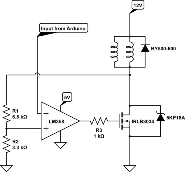
schematic

simulate this circuit – Schematic created using CircuitLab

The two diodes are for protection. The resistor divider is simply to account for the fact that the Arduino can only output 5V. My logic is as follows: If the voltage drop across the motor is too low, then the op-amp turns the mosfet on, allowing current to flow. If the voltage across the motors is too high, then the mosfet turns off.

My concern is that, rather than oscillating, the mosfet will just end up in a stable state, thus dispersing a lot of heat. Will this happen? If so, how can I make the circuit oscillate to avoid this problem?

Thanks!

\$\endgroup\$
1
  • \$\begingroup\$ To run at constant speed, given load variations, will require velocity feedback. \$\endgroup\$
    – Chu
    Commented Dec 24, 2016 at 15:31

2 Answers 2

0
\$\begingroup\$

Bad idea to use opamp to drive a gate. Much better to find a gate driver. Otherwise your system may overheat, suffer noises on input, etc. You will reduce the frequency to deduce heat, and the motor will stop working or will burn..

Also if you wand analov driver, you should better start with BJT instead MOSFET. Then indeed opamp may work (not sure about the specific opamp). Actually with MOSFET it works sometimes too, but for you will be easier to work with BJT, it's much more linear.

For analog driver you will need much more advanced control loop. But frankly i a little skeptical about describing it here. Google analog servo drive.

And last, but not least : for a brushed motor to keep the speed constant (or almost constant) just control it's voltage. Use some kind of variable voltage converter with current limit, and that's it.

\$\endgroup\$
0
\$\begingroup\$

You have to measure the current/voltage/speed (ideally speed, because this is the variable you want to stabilize) using the Arduino and generate PWM on the MCU. You can connect the MCU via a small resistor directly to the MOSFET.

In your current schematic you are trying to control the MOSFET in a linear way. It will dissipate lots of power. Motor drivers are usually controlled with PWM (I can think of only some audiophile turntables that have linear motor drivers).

\$\endgroup\$

Your Answer

By clicking “Post Your Answer”, you agree to our terms of service and acknowledge you have read our privacy policy.

Not the answer you're looking for? Browse other questions tagged or ask your own question.