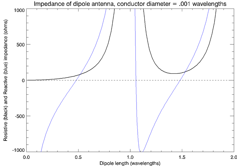
For a dipole antenna, half wave length is optimum size. Why is this so? What I understand is that radiation resistance of antenna is around 50 ohms at this size, which matches with the characteristic resistance of transmission line and hence less reflection loss. Is this reasoning correct? If yes, then why transmission line cannot have lower resistance? If no, what is the reason?
-
\$\begingroup\$ Well, unless you provide some details about your background and what you already know about this topic, the question is far too broad as it stands. \$\endgroup\$– Dave TweedCommented Dec 26, 2016 at 19:57
-
\$\begingroup\$ I have cleaned up some of the comments on this post. As a reminder to all, please be courteous to others. \$\endgroup\$– user22021Commented Dec 26, 2016 at 22:30
-
4\$\begingroup\$ Perhaps a good starting point is to understand the radiation pattern of the antenna: antenna-theory.com/antennas/halfwave.php \$\endgroup\$– Peter SmithCommented Dec 27, 2016 at 15:46
-
\$\begingroup\$ Peter - excellent link! \$\endgroup\$– AnalogKidCommented Feb 6, 2019 at 23:22
-
\$\begingroup\$ Portions of this question might be a dup of : electronics.stackexchange.com/questions/400665/… \$\endgroup\$– hotpaw2Commented Oct 31, 2020 at 15:44
3 Answers
Actually, a center-fed dipole that is slightly shorter than 1/2 wavelength (using the speed of light in a vacuum) might be considered "optimal". The reason why this is so, is that for such a dipole, the capacitative and inductive reactances cancel each other, making the impedance of the antenna purely resistive.
When the antenna has purely resistive impedance, the apparent power supplied to the antenna is equal to the true power supplied. An antenna for which this is not the case can also be an efficient radiator if the inductive or capacitative reactance is canceled by an external capacitor or inductor. Such an arrangement may be slightly less than ideal, however, because there will be circulating current between the antenna and the component used to balance the impedance. That is, there will be energy that is passed back and forth between the antenna and the component used to balance the impedance. Each time that energy is passed back and forth between the antenna and the balancing component, some energy is lost. This lost energy, in some cases, could be a significant fraction of the energy one is hoping to receive from the antenna, or hoping to transmit via the antenna. That, ultimately, is why an antenna which "naturally" has no reactive impedance at the receiving/transmitting frequency might be considered "optimal".
The following graph, taken from Wikipedia shows the reactive impedance crossing 0 at a point slightly below 0.5 wavelength. Notice that for antennas significantly shorter than that, the resistive impedance gets very small, while the (absolute) magnitude of the reactive impedance gets very large.
A couple things. First, a center fed dipole antenna that is slightly shorter than half wave length is in resonance, which means its impedance is purely resistive. Typically, its impedance is about 70 ohms.
I think by transmission line resistance you mean impedance. You can make transmission lines with impedances lower than 50 ohms, but these are not common. Most coaxial cable is either 50 of 75 ohms, with 75 ohm being less lossy for a given diameter.
The characteristic impedance of a transmission line is proportional to (the square root of) the ratio of inductance to capacitance (per unit length). So, to make a much lower inductance transmission line, you might need to make the wires thicker than the distance between their centers, which is very hard to do at reasonable costs and geometries.

