2
\$\begingroup\$

Me: Electronics enthusiast in the 1960s, little chance to practice since then.

Project: Schools in the UK have drawers full of expensive 'Data loggers'. Sophisticated and versatile devices with lots of plug-ins to measure and record mostly physics things. Rarely used because teachers don't use them often enough, crucial bit missing, can't get software to work etc.

A posible solution: Ultra-simple hardware with common software. The software I'm trialing is either Audacity or Acoustica audio editing software. Both are available for free, measure at 10kHz+ (plenty fast enough) and resolve to 16bit (again, plenty).

My current problem: I want to fire a narrow beam of visible LED light (not laser, regulations too complex) at a sensor to produce a signal that can be fed into the mic jack on a PC. The resulting pulse. These devices often used in pairs to start/stop a timer to measure acceleration etc but a single one could be used by reflection to count the rotation speed of a fan etc.

Photodiodes and Phototransistors are unknown to me and I have found comments on here (Q22414) like:

Photodiodes may be operated either forward or reverse biased. Forward biased gives most output. Reverse biased gives most speed. and is noisier. Reverse biased mode is most usually used.

I'm thinking that forward bias would be better for me, but where do phototransistors fit in? I suspect that photodarlingtons are a little slow. Help!

My ideal circuit has no IC's, a very low component count and is really cheap. That way any unskilled solderer has a chance of building or repairing it and if it gets lost/broken then it's not a big deal.

Thanks

Oops, I'm trying to reply to comments below but there is a short message length available.

I've got one device working already. A tiny box with 3 leads - one to USB as power supply, one to computer mic input and one with bead thermistor. Inside box is a 555 running at about 9kHz outputting to an R + 2.2V zener - this gives stable square voltage without risk of frying the mic input to computer. The output from that goes across another R + thermistor which gives me a square wave with amplitude varying with temperature.

In the audio editing program this looks like a continuous 'histogram' that goes up and down with temperature. Total cost of components about 5£$Euro, one equivalent is here:

http://www.data-harvest.co.uk/catalogue/science/secondary/data-loggers/secondary-science-data-logging/2404PK

http://www.data-harvest.co.uk/catalogue/science/secondary/smartq-sensors/smartqsensors/3100

My aim is probably not to improve, just simplify. There are already 'magic boxes' that do all the thinking to lots of decimal places , but these only teach the kids to use magic boxes - not to understand the underlying science. An example is the cooling curve of a molten solid. The liquid cools at a steady (not linear) rate but at the freezing/melting point the curve plateaus for a while and then drops again at the original rate. With my device the kids can calibrate the amplitude against a thermometer in different temperatures of water and draw a graph. This teaches more of scientific method than a magic box does.

My intention is to put the LED and the photodiode/transistor into black delrin tubes about 4-5cm long meaning that the beam direction can be deen for alignment but is not affected by ambient light.

It is unlikely that multiple sets of equipment will be use at the same time.

What I am really asking for is guidance on the relative merits of photodiodes compared with phototransistors. The data sheets mean little to me.

Thanks for the input everyone.

\$\endgroup\$
7
  • 1
    \$\begingroup\$ For a light gate I would recommend a suitabley driven IR LED (a 556 circuit, or (much simpler circuit) a microcontroller) with a lense + a TSOP-style reciever. (Or hack an IR remote control!) Getting a photodiode circuit to work will be much more work. \$\endgroup\$ Commented Dec 30, 2016 at 12:16
  • 4
    \$\begingroup\$ @hypfco The teachers aren't uneducated, our system puts them under too much stress atm and biologists are expected to teach physics etc. They simply don't have time to do the learning that they need. My aim is to simplify as much as possible. \$\endgroup\$
    – user134524
    Commented Dec 30, 2016 at 14:47
  • \$\begingroup\$ I've successfully used github.com/dkroeske/emon-server as an LED detector; the sensitivity can be tuned by adding a variable resistor in series with the existing resistor. \$\endgroup\$
    – pjc50
    Commented Dec 30, 2016 at 14:56
  • \$\begingroup\$ I removed my comment. \$\endgroup\$
    – Brethlosze
    Commented Dec 30, 2016 at 16:02
  • \$\begingroup\$ For fast time resolution over short (few cm max, preferably less) distances you may be able to use an umodulated LED. Over longer ranges you need to modulate the LED as in IR remote controls, and use a receiver that looks for the modulation in order to reject ambient interference. But then you need to look at the time response of the modulation detector to see what that does to your measurements. Consider that the time response may differ depending on signal level... Also, many modulation detectors expect the modulation to appear as brief pulses, and will reject its constant presence. \$\endgroup\$ Commented Dec 30, 2016 at 16:03

2 Answers 2

1
\$\begingroup\$

While your "wants" are commendable, you may have to make compromises for the following reasons:

  • Your optical system must work in a classroom, in competition with room lights.
  • Ideally, your light-emitter (LED) will be visible so that it can be well-aimed.
  • While long range might be a goal, you'd want many such optical gates to work in the same room without interference from others.
  • Using a PC's sound input limits you to 20 - 20kHz.

Wouter van Ooijen has a suggestion that meets some of your criteria. A very simple microcontroller can drive your light-emitting diode at any frequency you want. Some LEDs are packaged with molded-in lens that limits directivity while increasing range. A battery is required.
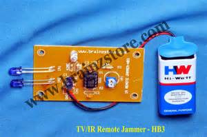
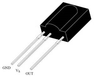
infrared transmitter The optical receiver is more difficult. A great many infra-red optical receivers are available for use as TV remote (or any appliance) receivers. These are universally limited to infra-red wavelengths, forcing you to use an infra-red LED that cannot be seen for aiming. These are three-pin receivers that require very little else than a battery and interface cable. It is possible that these can provide a signal to a PC's microphone input, detectable by Audacity. However, these chips are internally complex, and many will yield spurious outputs for two conditions:

  • A sustained period of no signal
  • A sustained period of full signal

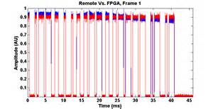
TV remote receiver optical detector These chips are designed to detect short bursts of signal such as those key codes transmitted by a TV remote. They detect the tone-burst modulation, and do not provide the carrier:
typical TV remote output signal

There are a very few versions of optical receivers that have simplified internal signal processing. Instead of actually detecting tone bursts, the photodetector signal is provided as output. Rather than detecting a specific frequency (usually found somewhere in the band between 30 kHz. - 60 kHz.) as TV remote receivers do, output frequencies from 20 kHz. - 60 kHz. are provided directly. Since 20 kHz. is acceptable to a PC's sound card input range, this type of receiver could provide a signal quite acceptable to a microphone, or line-in input. And Audacity could more easily recognize a 20 kHz. signal than the pulse edges provided by the more complex TV remote receivers. Audacity must now determine when the 20 kHz. is visible, and when it is not (this function is internal to the more complex receiver).

\$\endgroup\$
0
\$\begingroup\$

Well, I found a simple answer. As ever, ask Google the right question and you get the answer you need.

I was asking for Light Gates but in the US and elsewhere they are called Photogates and a search for 'photogates soundcard' gave me a lot of answers to my questions. In particular this paper: https://arxiv.org/ftp/arxiv/papers/1103/1103.1760.pdf which shows that I was trying to reinvent a well tried idea.

Thanks for your input.

\$\endgroup\$

Your Answer

By clicking “Post Your Answer”, you agree to our terms of service and acknowledge you have read our privacy policy.

Not the answer you're looking for? Browse other questions tagged or ask your own question.