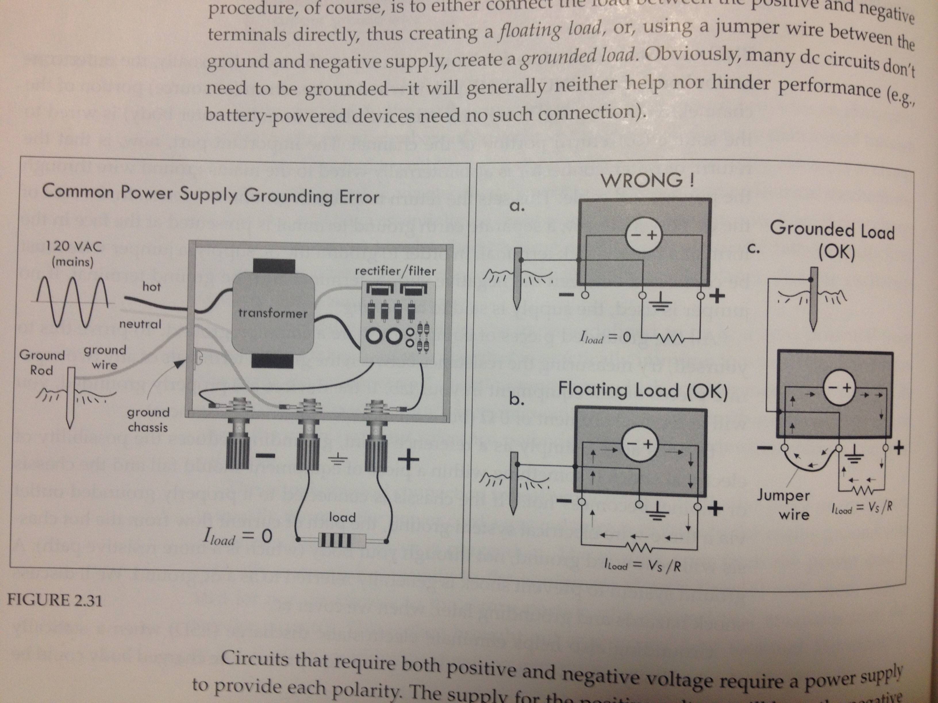
I've recently started reading through Practical Electronics for Inventors (Scherz and Monk 3rd edition), and have a few questions about a specific figure used when talking about grounding a circuit. Please bear with me.
The book notes how in 2.31a, there will be no current flowing from the power supply, as there is no current return path with the load being hooked up to the + and ground terminals of the power supply. In this case, wouldn't there still be some current flowing to ground until the supply runs out of juice, being that there's no return path for the electrons? There's still a very small amount of resistance in the wire correct? (I'm assuming in all these diagrams, the wiring for the ground and - leads are not actually connected, although the wires overlap in the diagram?)
Second, knowing that there has to be a return path for the current back to the supply, how is the current returning for the floating load? Looking at the left diagram, when the current goes through the load and has to go through the - terminal wire, does it go back all the way to the neutral wire, or does it loop through the transformer? What are the actual electrons doing in this situation, as opposed to conventional current flow?
Lastly, how is the jumper wire in the grounded load work exactly? Wouldn't the current seek straight to ground now that the jumper wire is there, like in 2.31a, rather than attempting to move across whatever internal resistance is within the rectifier/transformer?
I appreciate any help. Just trying to visualize these sorts of concepts.

