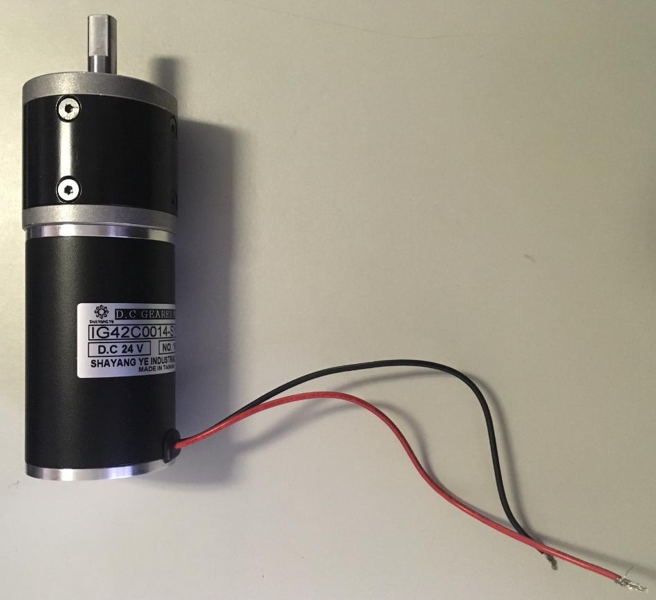
Two wire DC motors are polarity sensitive so you may want to consider a connector pair (one for the motor leads and the other mate to go on the PC board) that provide a keyed insertion scheme. This will prevent the connector from being joined in the wrong way.
Also when making the PCB design have a component outline on the silkscreen that shows the connector shape so as to help get the connector mounted correctly during board assembly. There are board mount connectors that have alignment pegs on the connector body that will rest in a drill hole on the PCB. This can ensure proper assembly. The optimum connector used will be a through hole mount type so it is ruggedly attached to the board.
For assembling the motor wire harness make up an assembly drawing that can be referenced to ensure the proper connection of the red and black wires to the proper connector pins. Not that the best connector for this application is one with crimp pin contacts that slide into the connector housing.
As to select which connector pair to choose within the above guidelines...it will depend on a number of factors including:
- Current carrying capability of the contacts needs to meet or exceed the motor current.
- You need to consider connector body size and how that relates to the space in your device package.
- Connector orientation for access will be important. Does it need to be vertical to the PCB or come off the PCB at right angles?
- How easy is it to mate and unmate the connectors for assembly and service.
- Some connectors are limited to a small number mating cycles so that needs to be taken into account relative to the application at hand.
- Does the mated pair of connectors have some type of locking or retention system to prevent the connectors from becoming unmated in environments with high vibration or flexing/tugging on the cable harness.
- Some applications have a voltage level of usage between the connector contacts. Make sure that the connector provides a higher rating than needed for the application.
- There can be a broad range of cost related to connector choices. Many of the other factors mentioned here can relate to the cost profile of the connector.
- Lastly I would strongly urge selection of a connector type that is unique in your application so that some other device in your subsystem does not get improperly attached in place of the motor.
- It can also be a very good idea to steer away from using connector types that are conventionally used for other applications. For example it would be best to avoid use of a USB connector for connecting the motor.
As you consider the above factors it will become obvious why there are so may thousands of different types of connectors out in the market. You may find a plethora of choices that will meet your needs.

