I power a 12V 0,84 W fan from a 5V power supply through MT3608 step-up converter. I would like the fan to work for about 5 seconds more after main power is down. Is it possible to do it using a capacitor? What should be its capacitance and connection to the fan?
-
\$\begingroup\$ P*t=deltaU^2*C/2 So you need a supercapacitor in the Farad range. \$\endgroup\$– winnyCommented Jan 24, 2017 at 22:10
-
\$\begingroup\$ If it isn't for accidental power loss then perhaps you could have a phased shutdown: shutdown the main circuitry and then five seconds later (or perhaps as determined by a temperature sensor) switch off the fan. \$\endgroup\$– Andrew MortonCommented Jan 25, 2017 at 11:54
-
\$\begingroup\$ yes, it is not for emergency but as I have run out of ATtiny85 pins I am not able to add "turn off" button (it is custom-made food dryer) \$\endgroup\$– KodakCommented Jan 25, 2017 at 12:22
-
\$\begingroup\$ It might be cheaper and take less space to add another ATtiny85 compared to using a large capacitor. \$\endgroup\$– Andrew MortonCommented Jan 25, 2017 at 18:15
-
\$\begingroup\$ I see 1F from japan for ~1$... \$\endgroup\$– KodakCommented Jan 25, 2017 at 19:25
1 Answer

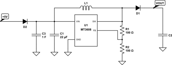
simulate this circuit – Schematic created using CircuitLab
You can power the MT3608 from a large capacitor on its input.
You will need a diode between the 5V supply and the capacitor to prevent the capacitor from back-powering the 5V supply once the 5V is off, . This could be either a schottky diode, or an ideal diode controller such as those made by Linear Tech.
Assuming you really get the 93% efficiency stated in the MT3608 datasheet, the input power will be 0.84W / 0.93 = 0.903W.
You say you want to power the fan for 5s, so the total energy is 5s * 0.903W = 4.515J.
The MT3608 has a 2V to 24V input range.
If the capacitor is to supply power to the fan, the energy lost by the capacitor will be equal to the energy input to the converter to power the fan, which is 4.515J.
The initial voltage on the capacitor is 5V minus a diode drop. Lets assume the initial voltage is 4.5V. The final voltage is 2V, which is the lower limit of the input range for the MT3608. So...
0.5 * C * ((4.5V)^2 - (2V)^2) = 4.515J
So C = 4.515J * 2 / ((4.5V)^2 - (2V)^2) = 555mF.
So you need a capacitor rated to at least 5V and 555mF.
You will need to size the capacitor larger than 555mF to account for any voltage drop on the output due to the internal ESR of the capacitor, as well as decreasing efficiency on the converter as the input voltage gets lower.
-
\$\begingroup\$ Sorry for noob comment but can you show me a wiring of supercap with schottky diode? \$\endgroup\$– KodakCommented Jan 25, 2017 at 9:23
-
\$\begingroup\$ thank you; I understand that D2 and C3 are elements additional to U1 application note, right? How about current limiting - I have read that caps can draw much current - shall I limit it somehow for my 800mA 5V power source? \$\endgroup\$– KodakCommented Jan 25, 2017 at 12:19
-
2\$\begingroup\$ Current limiting should be added. \$\endgroup\$– user4574Commented Jan 25, 2017 at 16:54
-
1\$\begingroup\$ @Fredled Charging a capacitor to a higher voltage would store more energy per Farad of capacitance, but a capacitor rated for a higher voltage is likely to be larger in proportion to the extra energy. In fact a 5V 4F capacitor and a 10V 1F capacitor of the same type are likely to be about the same physical size. Usually each dielectric material has a maximum amount of energy per unit volume that it can store. Starting from a higher voltage can allow you to use a higher percentage of the capacitor energy before the output voltage becomes too low. So you may come out slightly ahead. \$\endgroup\$– user4574Commented Feb 18, 2019 at 1:14
-
1\$\begingroup\$ @Fredled As for using a resistor on the output that would just waste power so I wouldn't recommend it. On the input side a resistor could be good for limiting inrush current to initially charge the capacitor. But that configuration must be used with an extra or-ing diode. \$\endgroup\$– user4574Commented Feb 18, 2019 at 1:15
