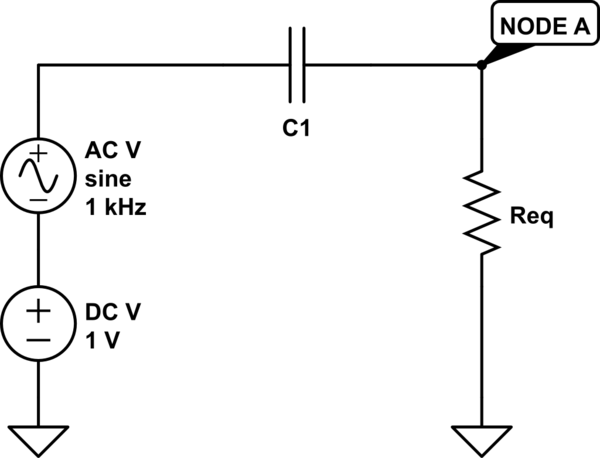
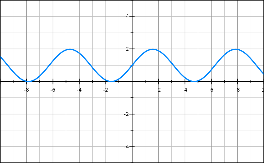
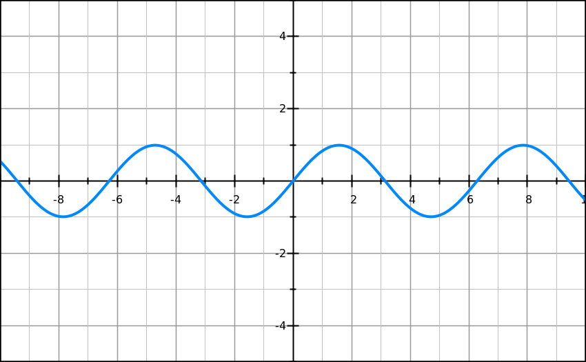
If you want to use a capacitor as a DC-blocking element (i.e., in series with the signal source) you should choose its capacitance value according to:
- AC signal frequency f;
- Equivalent Resistance Req seen from "NODE A" (see figure below) to GND.

simulate this circuit – Schematic created using CircuitLab
Why that? As someone else put it already, the role of the capacitor is to implement an high-pass filter, meaning that high frequency components are passed and low-frequency ones (like the DC) are blocked.
Unfortunately, this filtering is not restricted to the DC (0Hz) component, since in most cases you have a load of finite value to drive (resistance Req in the schematic), so also low-frequency AC components will be attenuated by some extent. Remember that the -3dB frequency of an RC filter (high-pass or low-pass) is:
$$f_{-3dB}=\frac{1}{2 \pi C R_{eq} }$$. This means that at that frequency your signal gets attenuated by 3dB (and at lower frequencies the attenuation will be even stronger). Therefore, the capacitor value should be chosen large enough in order not to cut off the lowest frequency component of interest (1 kHz in your example). In other words, you must end up with a -3dB frequency sufficiently lower than 1 kHz , so that this frequency is not attenuated too much.
A good way to make sense of this is to consider how a capacitor is built: basically, there are two conductive plates separated by a dielectric. It is straightforward to figure out that a DC current won't never flow through it... Rather, current through a capacitor is possible if the voltage across it changes over time (and that's the case for higher frequency signals). Roughly, the higher the frequency and the capacitance value, the larger the capacitor current, so the smaller the signal blocking capability.


