I have one power source (bicycle dynamo) A.C 5-6V which will be rectified to D.C, and the other source D.C from a solar panel 12V. It will be 2 input source and one output. what type of power switch would work best for this circuit? MOSFET BJT or any other? The output will be to a handheld device of 12V Thanks for your time.
-
2\$\begingroup\$ How will a 6 volt AC output become 12 volts dc with just a rectifier? \$\endgroup\$– Andy akaCommented Feb 17, 2017 at 14:48
-
\$\begingroup\$ via transformer before rectified to 12V \$\endgroup\$– PeterrrrrrrCommented Feb 17, 2017 at 21:09
2 Answers
The most simple way of doing this is with two diodes, each one in series with each one of the voltage sources. The lower the forward voltage of the diodes, the better the solution. Since this is the case, the market also offers MOSFET based "active ORing diodes", like this one from TI
-
\$\begingroup\$ Two diodes can't help if the voltage of those two source voltages are very different. \$\endgroup\$– UweCommented Feb 17, 2017 at 20:08
-
\$\begingroup\$ @Uwe of course they will help since the idea is that one of the sources will be active, not both of them \$\endgroup\$ Commented Feb 17, 2017 at 20:16
-
\$\begingroup\$ one source will be stepped up to 12V via transformer, I should've have made it clearer, so both inputs will be 12v \$\endgroup\$ Commented Feb 17, 2017 at 21:16
-
\$\begingroup\$ @Claudio: It is possible that the bicycle dynamo and the solar panel are active both at the same time. \$\endgroup\$– UweCommented Mar 7, 2017 at 10:00
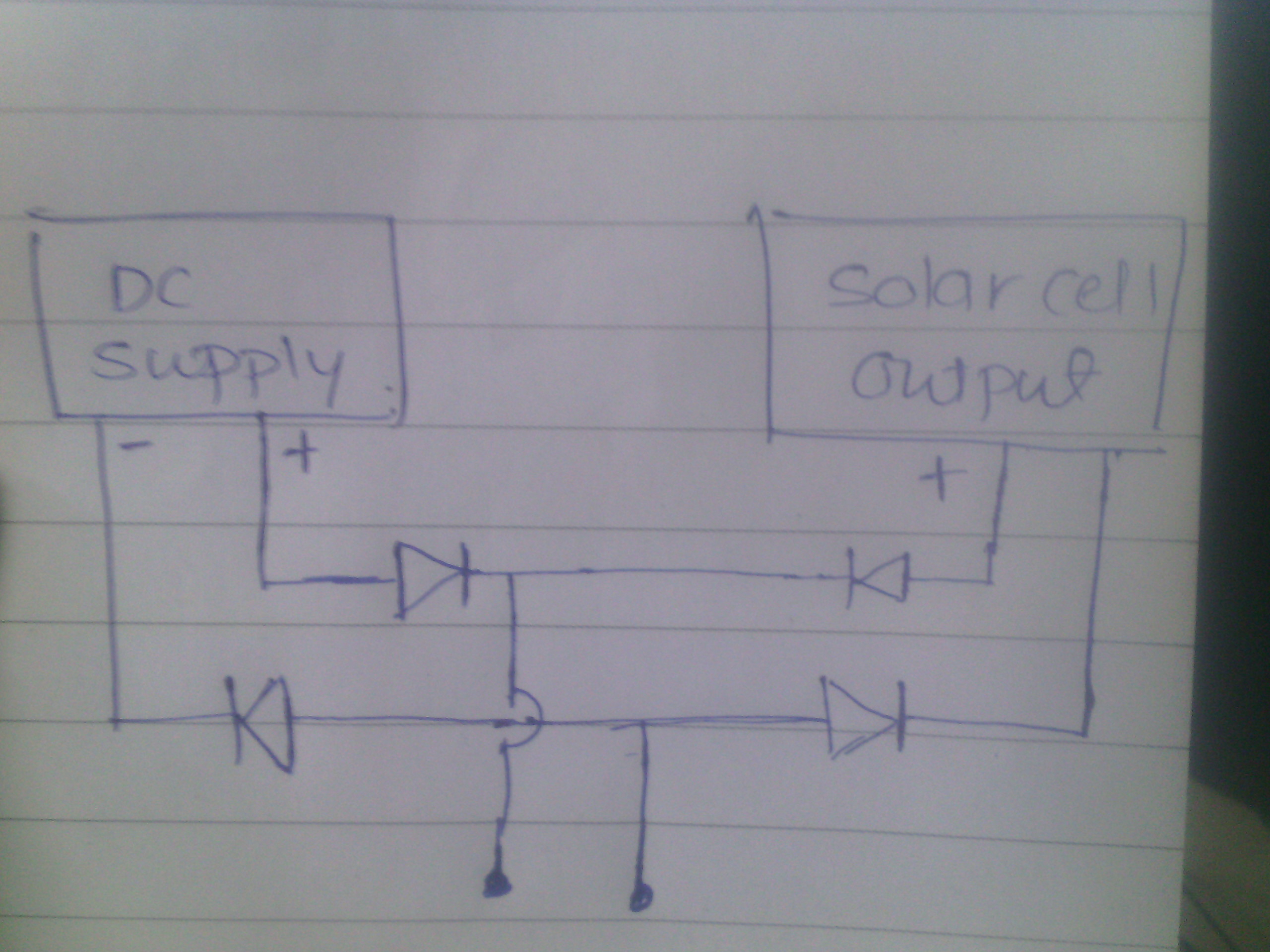
Connect diode to each pin coming out from that dc supply and also do same with solar cell output wires but make sure that diodes are connected in forword bias means p to p and n to n .now connect postive supply of solar cell to positive of dc supply n n negetive to negetive . 
-
1\$\begingroup\$ @VishayShinde The additional diodes at the negatives are not needed. It is not only not needed but also it is not good since the losses are now twice what they would be if you connected the negative side together and used only diodes for the positive. \$\endgroup\$ Commented Feb 17, 2017 at 20:41
-
\$\begingroup\$ thanks, very helpful diagram. what type of diode? \$\endgroup\$ Commented Feb 17, 2017 at 22:14
-
\$\begingroup\$ You can use either simple diode or schottky diode \$\endgroup\$ Commented Feb 18, 2017 at 3:14
-
\$\begingroup\$ @claudio avi chami you can also connect that negetive supply directly I added them just for extra protection \$\endgroup\$ Commented Feb 18, 2017 at 3:21
