1
\$\begingroup\$

I have been working on an Active Low-Pass filter (2-pole Sallen-Key configuration) for a Low Frequency Oscillator (LFO) on a synthesizer project. I had a problem with a recent build that I have managed to trace to a change in the Op-Amp manufacturer. The original TL072CD (Texas Instruments) has been replaced by a TL072IDT (STMicro) and resulted in a misshapen LFO waveform, post-filtering.

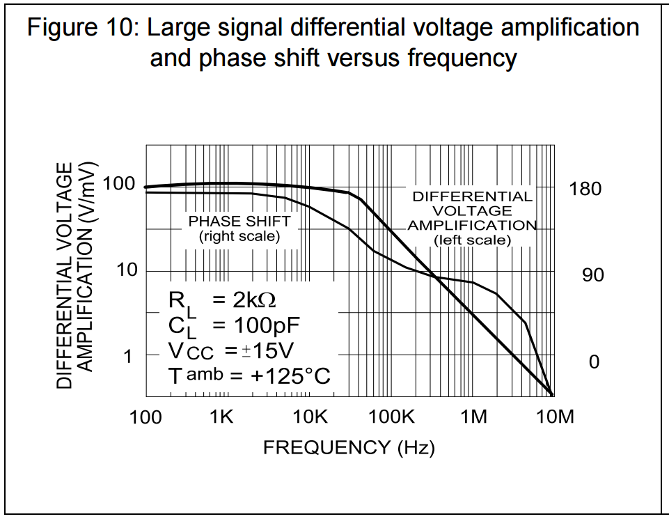
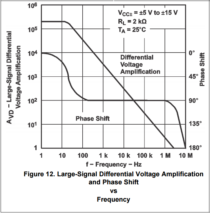
Looking through the datasheets, the only significant difference that I can see between the two parts is the phase shift:

TL072CD - Texas Instruments: TL072CD Texas Instruments - Phase Shift Diagram

TL072IDT - STMicro: TL072IDT STMicro - Phase Shift Diagram

It appears that there is a 180 degree phase shift difference between the two TL07x's at low frequencies. I would expect this amount of shift to drastically alter the performance of my filter, especially at very low frequencies (The LFO will operate @ < 1Hz). However, the inconsistencies between phase-shift diagrams could be misleading me. Could anyone clarify this for me? Has anyone encountered a similar problem with differences between op-amp manufacturers?

\$\endgroup\$
2
  • 1
    \$\begingroup\$ Just two points: The TI data has always looked rather idealized, an artist's rendition if you will. The ST data at least looks like it came from test measurements. Second, these seem like really different amplifiers. Based that is on the open loop 3db gain bandwidth and the phase shift. You probably need to redesign your filter using new device characteristics. I always try to avoid this sort of thing by using more conservative filter designs. Plus I have the luxury of tiny production runs so the source never changes part way through. \$\endgroup\$ Commented Mar 6, 2017 at 17:40
  • \$\begingroup\$ Don't know where your low-frequency oscillator is oscillating, but the TIamp has gain of 300 @ 10kHz, STamp has gain of 100,000 at the same frequency. \$\endgroup\$
    – glen_geek
    Commented Mar 6, 2017 at 18:11

1 Answer 1

3
\$\begingroup\$

It is surprising, but the second graph shows the inverting gain - measured with a test signal at the inverting input (because the phase shift is -180deg for low frequencies, including DC). This is rather uncommon but creates no problem at all (normally, the non-inv. gain is given with 0 deg. for low frequencies). So - this difference does not mean anything.

More important is the phase shift at the frequency for unity gain. This value determines the distance of the loop gain phase from the critical value (in case of unity gain feedback). This critical value is -180deg for the 1st diagram and 0 deg for the 2nd diagram. This difference is called minimum PHASE MARGIN PM. For PM=0 the circuit with unity gain feedback is unstable.

In the first diagram we have app. PM=(180-100)=80 deg. and from the 2nd diagram we derive PM=(45-0)=45 deg.

Hence, as far as the phase margin (stability margin against self-oscillations) for unity gain feedback is concerned, the first device is better (more stability margin).

\$\endgroup\$

Your Answer

By clicking “Post Your Answer”, you agree to our terms of service and acknowledge you have read our privacy policy.

Not the answer you're looking for? Browse other questions tagged or ask your own question.