0
\$\begingroup\$

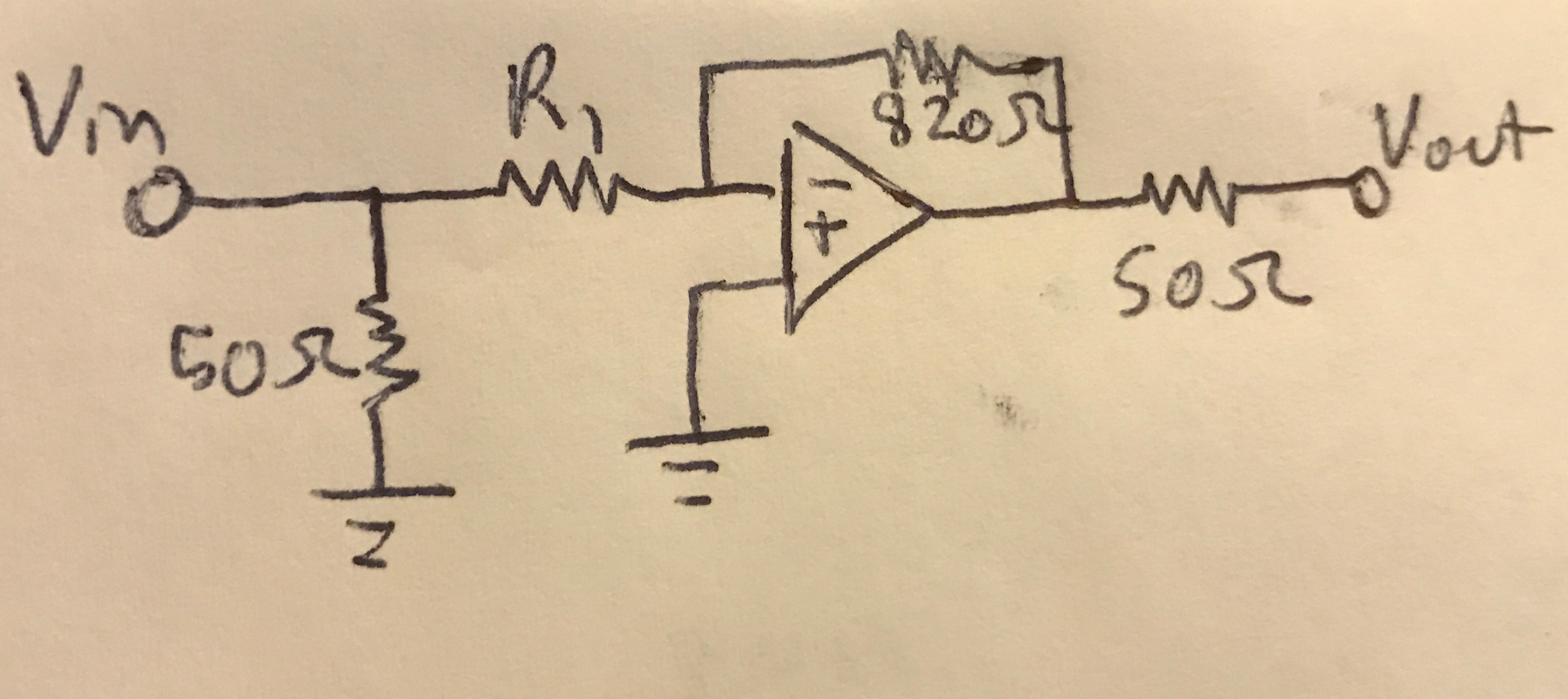
I am using an LM6181 op-amp to try and build an inverting amplifier and implementing this circuit with a breadboard. I am struggling to set the gain as I wish. For simple testing I am using a function generator as the input with an impedance of 50 ohms, and simply producing a 1 MHz sine wave. The circuit I am using is this (not shown are two bypass capacitors in parallel of .1 uF and .01 uF for each bias pin):

enter image description here

R1 alters the output but not as expected fully. When R1 is also equal to 820 ohms, I observe a signal. When R1 is equal to 50 ohms, I observe a signal ~10X larger.I tried multiple resistors for R1 between 50 ohm and 820 ohm (200, 330, 560, 670 ohm) and all yielded the same severely attenuated signal (changing the resistor does not alter the signal). In fact, this signal is the same as when R1 is removed. Interestingly, the amplitude of this signal increases when the frequency of it increases too.

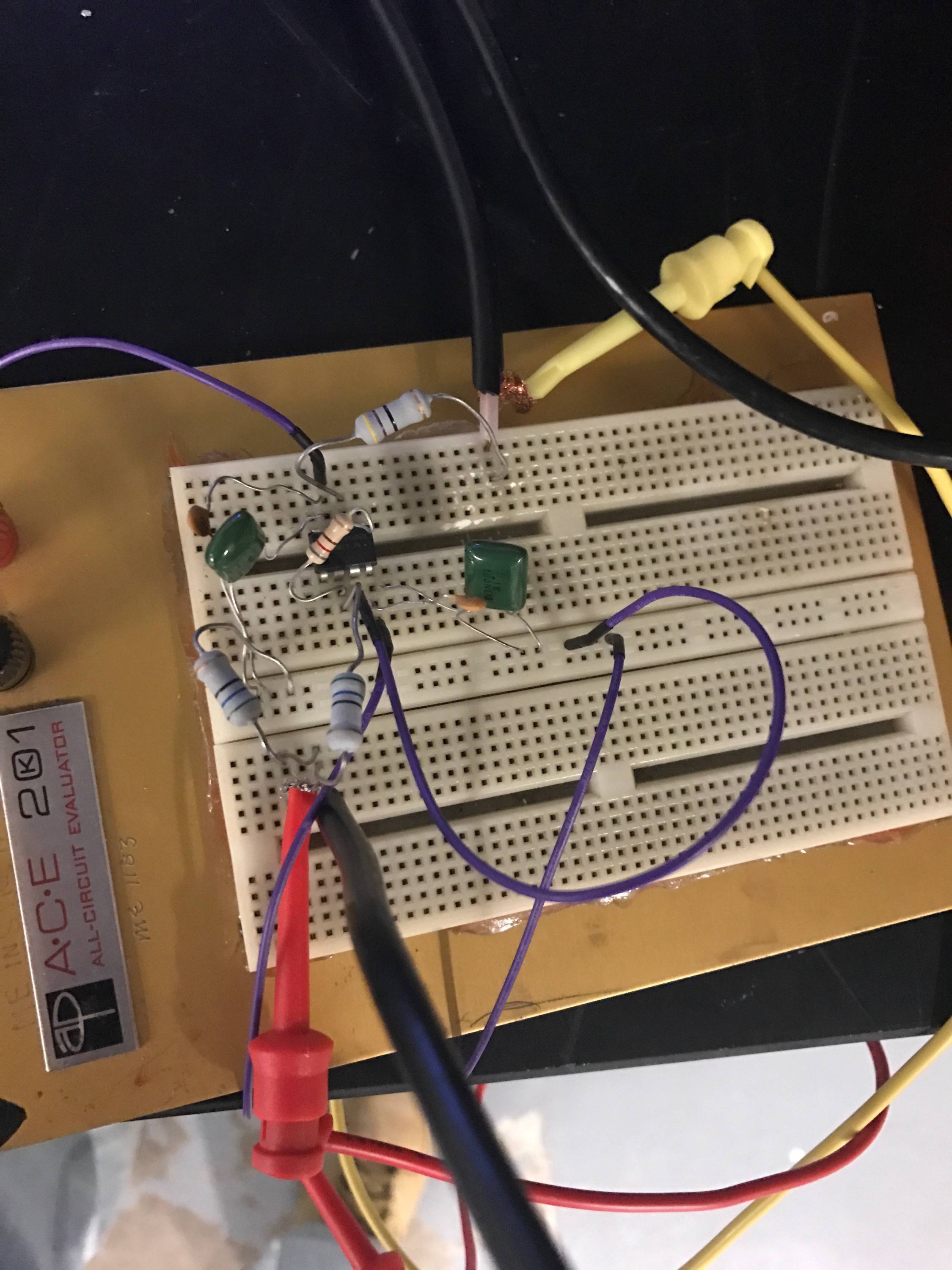
What could be causing these problems such that only 50 ohm and 820 ohm resistors produce an output as expected? I also tried a different signal source, using a silicon photomultiplier (essentially a photodiode) that to my knowledge does not have exactly a 50 ohm output impedance and observed the same effects. Below is my actual implementation.

enter image description here

I'd add more pictures but I can only have two links, sorry!

\$\endgroup\$
4
  • \$\begingroup\$ Do the other resistors have thinner leads? It sounds like you're not making connection in the breadboard. \$\endgroup\$
    – user16324
    Commented Mar 10, 2017 at 21:25
  • \$\begingroup\$ Please delete this question or your other one as they are too similar and duplicate questions are not allowed. Thanks \$\endgroup\$
    – Voltage Spike
    Commented Mar 10, 2017 at 21:33
  • \$\begingroup\$ You may have better success by configuring the amp as non-inverting. That will let you considerable reduce the length of signal wires. You should also bend and cut your resistor wires. At 1Mhz your breadboard is not a nice environment with long leads. \$\endgroup\$ Commented Mar 10, 2017 at 21:48
  • \$\begingroup\$ If you place 50 ohm resistor at R1 then input impedance of this circuit will be 25 ohms. Do you calculate with it? \$\endgroup\$ Commented Mar 11, 2017 at 6:19

2 Answers 2

1
\$\begingroup\$

This is a fast (50 MHz, 2000V/µs) opamp. These tend to have a strong dislike for high parasitics like L in the supply or C in the feedback. On a breadboard, it might oscillate or do weird stuff, but since you post no traces, there is no way to tell.

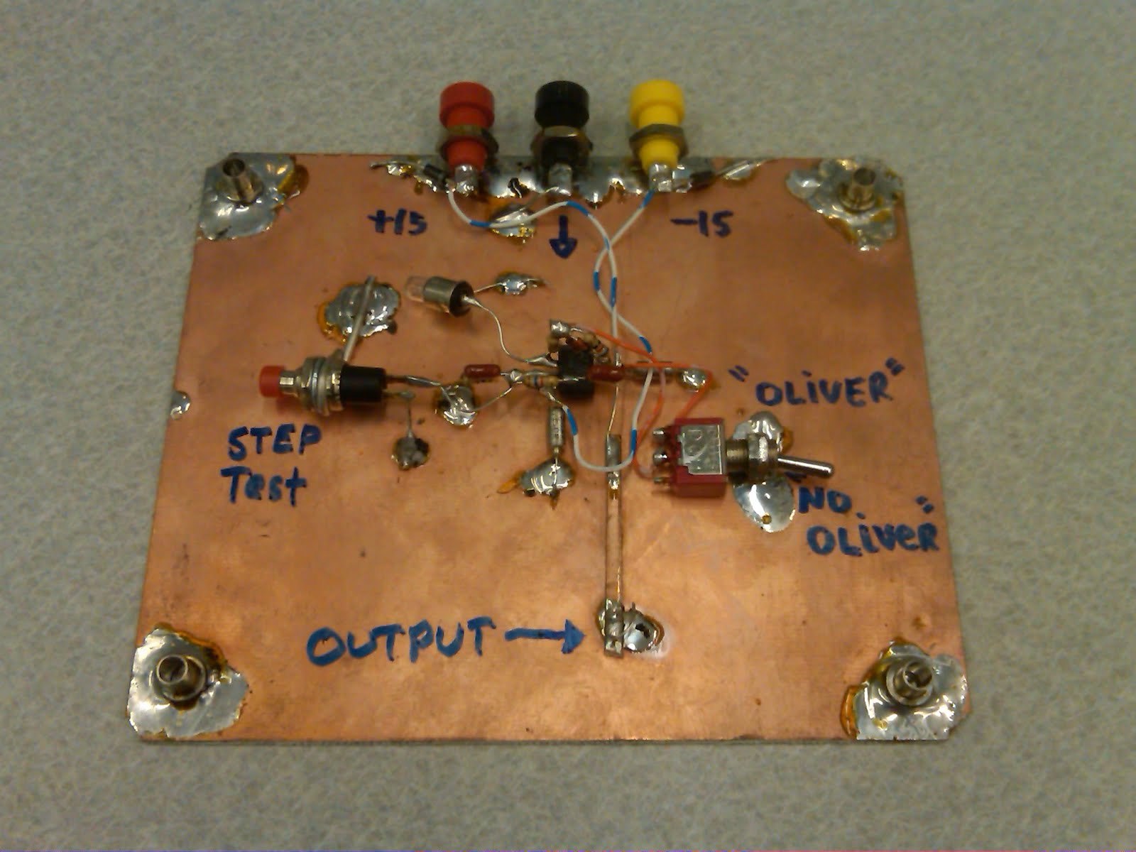
You need a real PCB. If you want to prototype it, solder it dead-bug on a ground plane, like so:

enter image description here

Source

Now, it is also a current feedback opamp. Since you don't mention it, I will suppose you know the differences with a voltage feedback opamp...

Also... come on, look at that yellow wire, it's about five miles long, and it's the GROUND of the test signal coax! And you're testing that at 1MHz?

\$\endgroup\$
2
  • \$\begingroup\$ This doesn't explain why the circuit worked with gain of -1 and gain of -16. \$\endgroup\$
    – The Photon
    Commented Mar 10, 2017 at 21:52
  • 1
    \$\begingroup\$ I'm dying to know the difference between "Oliver" and "No Oliver". \$\endgroup\$
    – uint128_t
    Commented Mar 11, 2017 at 0:47
0
\$\begingroup\$

When R1 is also equal to 820 ohms, I observe a signal. When R1 is equal to 50 ohms, I observe a signal ~10X larger.I tried multiple resistors for R1 between 50 ohm and 820 ohm (200, 330, 560, 670 ohm) and all yielded the same severely attenuated signal (changing the resistor does not alter the signal).

You broke something.

Maybe the op-amp, maybe the connection between the op-amp and one of the resistors, maybe the power supply. We can't tell from here. But the expected behavior is for the gain to change smoothly as R1 is changed. If that's not what you see, something about your physical circuit doesn't match your schematic.

\$\endgroup\$

Your Answer

By clicking “Post Your Answer”, you agree to our terms of service and acknowledge you have read our privacy policy.

Not the answer you're looking for? Browse other questions tagged or ask your own question.