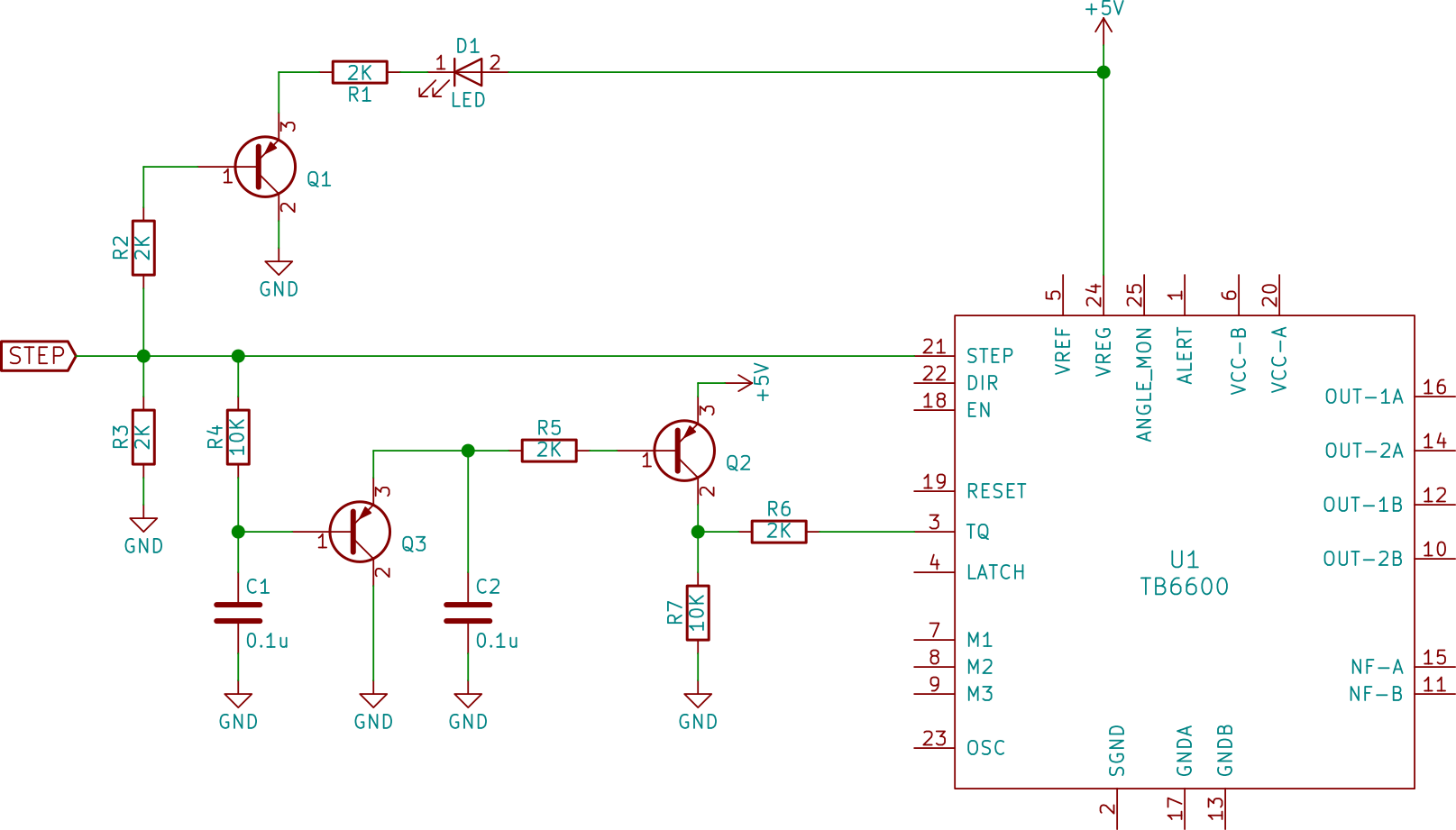
This is a part of the schematic for a chinese built TB6600 stepper driver. The TQ pin (torque setting) can be either LOW when the torque is reduced to 30% or HIGH when its 100%. How does this part of the schematic work? STEP signal is the clock signal that turns the motor by a single step. No part numbers for the transistors were provided but I'm guessing they are something similar to a 2N3906(?).
2 Answers
Looks like those transistors simply delay the step signal and apply it as the current demand.
If you step fast enough it will stay in high current, and if you single step it goes into holding current mode shortly after each step.
This circuit is designed to reduce the power to your stepper motors when they are idle to prevent overheating. It does this poorly. Adding a 1N914 diode placed in parallel with R4 will guarantee that the high torque condition is active on every pulse. As it is now it takes several steps to set high torque with a typical 25KHz clock rate. Increasing C2 to 1uf will provide a somewhat longer high torque state to stay active for the slowest of motion. Adding a 10K resistor between the emitter and base of the Q2 transistor would add thermal stability to the timing and give a crisper and more reliable transition to idle. The low torque state should only be active when the CNC is idle. Consider the typical operation of carving a plaque using the raster method. One axis is effectively idle (low torque mode) for a considerable period of time while the other axis is cutting. The main tool forces are pushing directly against the idle stepper motor. The motor with low torque is at risk of slipping. I would think an idle timer should be in the order of a full minute instead of the 3 to 5 milliseconds represented in this circuit. Thanks, Bill

