0
\$\begingroup\$

I'm trying to make the voltage reference for an INA214 opamp selectable between GND, 4.5V and 10V. I'm using a CD4051B multiplexer.

However, the 10V VREF gets pulled down to 5.84V, and I can't figure out why.
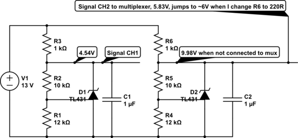
schematic

simulate this circuit – Schematic created using CircuitLab

CD4051B has:

  • INH, Vee, Vss to GND
  • C to GND
  • A, B to 5V (thus selecting CH3 as output)
  • CH3 to GND
  • CH1 to D1 output
  • CH2 to D2 output
  • Output measured by multimeter

Output measures:

  • 4.95V when D2 is connected to any pin on the mux
  • 0V when D2 is not connected
  • 4.54V when B is GND, no matter if A is 5V or GND (D2 is not connected)

which is strange, because CH1 is A=1 B=0.

What is going here? Are the TL431s interfering with the function of the CD4051B, or...?

By the way, am I required to connect the other pins/channels to ground, or can they be floating?

\$\endgroup\$
18
  • 2
    \$\begingroup\$ You don't say what you're powering the CD4051 with. I'm going to guess that it's 5V - in which case the problem is obvious - you can't pass voltages higher than your supply. \$\endgroup\$
    – brhans
    Commented Mar 27, 2017 at 18:40
  • \$\begingroup\$ @brhans, I read the following, from the datasheet, as though 4.5V Vcc would allow up to 20V channel input. Am I mistaken? "Control of analog signals up to 20V P-P can be achieved by digital signal amplitudes of 4.5V to 20V (if V DD -V SS = 3V, a V DD -V EE of up to 13V can be controlled; for V DD -V EE level differences above 13V, a V DD -V SS of at least 4.5V is required). For example, if V DD = +4.5V, V SS = 0V, and V EE = -13.5V, analog signals from -13.5V to +4.5V can be controlled by digital inputs of 0V to 5V." \$\endgroup\$ Commented Mar 27, 2017 at 18:47
  • \$\begingroup\$ But maybe this is only for signals of negative voltage? \$\endgroup\$ Commented Mar 27, 2017 at 18:50
  • 1
    \$\begingroup\$ I've generally learned to ignore anything in a datasheet which looks like it was written by someone in the marketing dept and focus on the tables, figures & diagrams ... \$\endgroup\$
    – brhans
    Commented Mar 27, 2017 at 18:59
  • 1
    \$\begingroup\$ Yes, you will need voltage translation. I suggest using simple NPN transistors as open collector, with pullup resistors. \$\endgroup\$
    – bobflux
    Commented Mar 27, 2017 at 19:09

1 Answer 1

2
\$\begingroup\$

As stated in comments, issue has to do with supply voltage to device and fixing that screws with the logic levels requiring additional components which makes the rationale for using the device itself suspect.

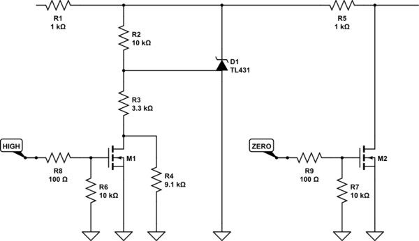
Alternative: Use two low RdsON MOSFETS to change the bias on the TL431 and or short the reference to ground.

schematic

simulate this circuit – Schematic created using CircuitLab

\$\endgroup\$
2
  • \$\begingroup\$ Is R5 necessary? Without it, wouldn't D1 just be bereaved of its supply? And this would also lower the output impedance? \$\endgroup\$ Commented Mar 27, 2017 at 20:01
  • \$\begingroup\$ @user95482301, I added that to drop the current a little, figured you were using batteries like everyone else these days seems to be. I was assuming high impedance input to your op-amp so it should not matter. But is safe to remove it otherwise. \$\endgroup\$
    – Trevor_G
    Commented Mar 27, 2017 at 20:10

Your Answer

By clicking “Post Your Answer”, you agree to our terms of service and acknowledge you have read our privacy policy.

Not the answer you're looking for? Browse other questions tagged or ask your own question.