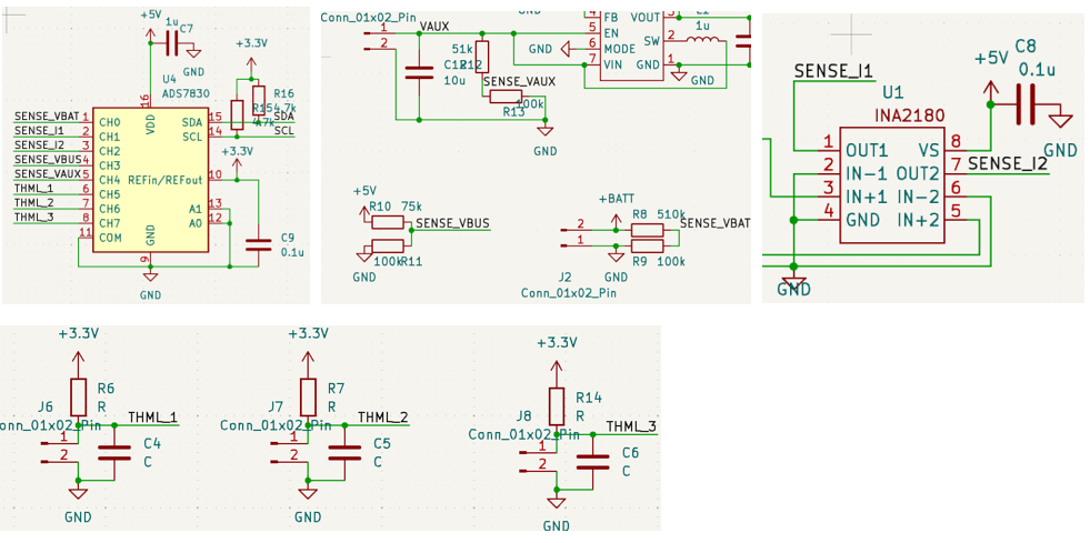
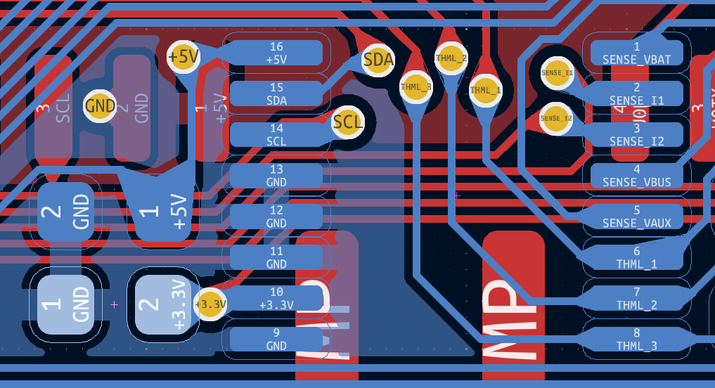
I made a board to read some analog values using an ADS7830 ADC. I wish to use a 3.3 V source as external reference voltage.
The schematic and layout are shown below (R6, R7, R14, C4, C5, and C6 connected to three THML pins are NOT soldered, VAUX pin is NOT connected to the battery), and there is a 0.1 μF capacitor (C9) to stiffen Vref (tested on oscilloscope, it has almost no ripple).
The channels are connected as below:
| Channel | Connection |
|---|---|
| CH0, CH4 | Pulled to GND with hundreds-kΩ resistors |
| CH1, CH2 | Outputs of current sensing amplifier, 0 V here |
| CH3 | 2.8 V from voltage divider |
| CH5 | Directly short-circuited to GND |
| CH6, CH7 | Floating |
The write commands and read values are below. Internal reference is turned off by {PD1,PD0} = {0,1}, but the read values are strange and it looks like an almost 0 V reference is somehow applied.
cmd = 0b10000100
CH 0 = 127
cmd = 0b11000100
CH 1 = 3
cmd = 0b10010100
CH 2 = 15
cmd = 0b11010100
CH 3 = 255
cmd = 0b10100100
CH 4 = 0
cmd = 0b11100100
CH 5 = 255
cmd = 0b10110100
CH 6 = 0
cmd = 0b11110100
CH 7 = 0
However, if I set {PD1,PD0} = {1,1} (i.e., turn on the internal reference), the ADC functions normally and accurately (though CH3 will saturate, as it is tested normally with Vin = 0~2.5 V on other channels).
The first time, I accidentally set the command to turn on the internal reference. The datasheet says "If using an external reference, PD1 must be set to ‘0’, and the external reference must be settled", but it does not mention what would happen if it is wrongly set.
Is anyone facing the same issue, and is there a possibility that turning on the internal reference with the external reference connected to a higher source burns the IC and hence causes the problem?


