1
\$\begingroup\$

So many academic papers quote the following fact: "A line commutated converter in steady-state operation inherently consumes reactive power of about 60% of the DC power transferred."

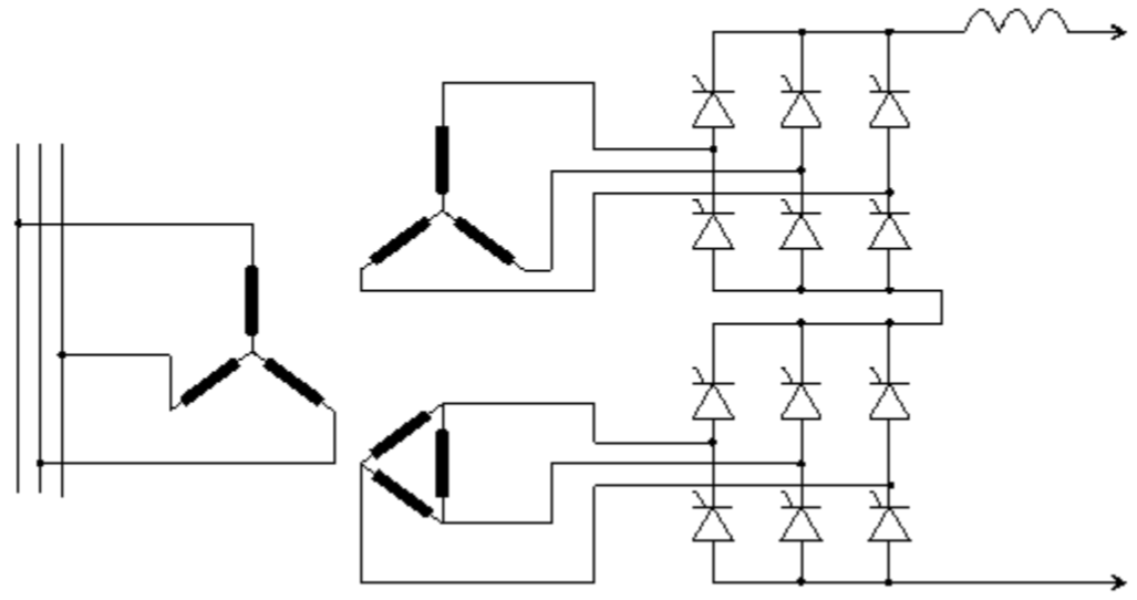
I do not want to see this from "generating" or "consuming" vars' view. My real question is more like this: HVDC is causing current to phase shift from the voltage, what is causing the phase shift?

commutation process itself? or the reactive elements in filters, transformers and the transmission line?

I strongly believe that alpha angle in the commutation process is NOT the answer. I think, the fundamental of reactive power is the fact that I and V are out of phase. Alpha angle blocks the occurrence of current, it does not cause phase shift. blocking and phase shift are very different!

For example, imagine a simple circuit with an AC source and a resistor in series. if a diode is inserted between the AC power source and the resistor, current may be blocked for half a cycle, (strictly speaking, more than half a cycle. Since the diode will only start conducting @ 0.7-ish volt, we technically have a none zero alpha angle here as well), but the current is still in phase with the voltage, no phase shift, no Var.

I find this frustrating, as most of you just accept the conclusions "var is due to alpha angle" without truly thinking it thru. I highly suspect that, at normal load of an HVDC line, the transmission line is a huge inductance, and that's the reason for the reactive power consumption.

\$\endgroup\$
0

2 Answers 2

5
\$\begingroup\$

Becase of said alpha. You always lead the current due to that fireing angle and then smooth it out with reactors but you still end up leading current over voltage. Hence reactive power.

\$\endgroup\$
5
  • \$\begingroup\$ when alpha is zero we should have 0 reactive power then? When alpha angle changes from 0 to 90, we should expect wild swing of reactive power consumption then? I don't think that's the case in reality. \$\endgroup\$
    – eliu
    Commented Mar 31, 2017 at 21:54
  • \$\begingroup\$ At zero alpha you have no consumption/generation. At 90 degrees, you have completely lost control but have again no reactive power. Most LCCs have a narrow span if allowed alpha between 10-50 degrees and thus always very reactive. \$\endgroup\$
    – winny
    Commented Mar 31, 2017 at 22:08
  • \$\begingroup\$ I am challenging the idea that "allowing conduction only when voltage is at certain level" (aka, controlling the alpha) causes current to lag voltage (aka, generating reactive power). Most literature cites "0.6 of VAR needed for for every WAT transmitted". if during normal operations, alpha can change between 10-70 degrees, and alpha angle is the CAUSE of var, shouldn't the assertion be "a range of something VAR is needed for every WAT"? instead of a almost fixed 0.6 ratio between Var and Wat. \$\endgroup\$
    – eliu
    Commented Jul 5, 2017 at 18:28
  • \$\begingroup\$ Of course! Don't know where you dug up that 0.6 figure, but it's just a rule of thumb. In pratice you will gave switchable banks of VAR compensation which you will turn on and off depending on you load and thus alpha. \$\endgroup\$
    – winny
    Commented Jul 5, 2017 at 20:36
  • 1
    \$\begingroup\$ @eliu: What's a WAT? A 'watt' (W)? \$\endgroup\$
    – Transistor
    Commented Aug 6, 2017 at 7:57
1
\$\begingroup\$

2.4 Shunt Capacitors

A line commutated converter in steady-state operation consumes reactive power of about 60 % of the active, or d.c., power transferred. The shunt capacitors installed at the converter a.c. bus supply the reactive power required to maintain the converter a.c. bus voltage. To achieve satisfactory power factor for the LCC HVDC converter, the shunt capacitors are normally subdivided and switched by circuit breakers as the d.c. power varies. Some or all of the shunt capacitors are normally configured as a.c. harmonic filters.

AC to DC convertors.

Their use of consume is general. To convert from 3-phase to dc for HVDC transmission, they are using transformers in delta and wye. The transformers are consuming the VARs in the sense the source has to provide it. Reactive power goes back and forth between the source and load. Hence the section on power factor shunt capacitors.

Furthermore, it provides independent control of the reactive power at the two ends and independently of the active power transfer over the d.c. transmission.

But the load side must also meet the requirements of the load. There is no direct connection between source and load with reference to real and reactive power because of the dc transmission. So both ends of HVDC link needs active control of reactive power to meet source and load needs.

DC Transmission Using Voltage Sourced Converters

\$\endgroup\$

Your Answer

By clicking “Post Your Answer”, you agree to our terms of service and acknowledge you have read our privacy policy.

Not the answer you're looking for? Browse other questions tagged or ask your own question.