1
\$\begingroup\$

I'm working on a project in which a solenoid valve needs to be triggered when a sensor detects a passing object. I have the concept and general design down, however I need some help with the specifics.

Essentially, a photoelectric retro-reflective sensor will detect an object, send its signal to a relay which in turn will trigger a 24 Vdc solenoid valve.

  • The sensor's signal voltage is listed as approximately Uv / < 3V and output current Imax is 100 mA

Sensor Datasheet

  • The solenoid is 24 Vdc and 8W, with an inrush VA of 25 and hold VA of 14.5

Solenoid Datasheet

  • 24 Vdc power supply is to be used

Question 1: What data do I need to consider (from that listed above or otherwise) when choosing a relay? Specific relay suggestions are welcome :)

Question 2: Once the relay has been chosen and provided its specs suit the sensor and solenoid, is any further circuitry required i.e. a diode for the inductive load etc?

As is probably evident from my questions I'm quite inexperienced in this area so sorry for any ambiguity but thank you, your help is much appreciated!

\$\endgroup\$
6
  • \$\begingroup\$ You need a relay that switches at least 24V and 25A with a coil rated for 3V maybe 2.5V. Yes you need a 25A+ fly-back diode across the output of the solenoid to protect the contacts, and a 1A fly-back on the coil side to protect the sensor. \$\endgroup\$
    – Trevor_G
    Commented Apr 6, 2017 at 2:03
  • \$\begingroup\$ VA of 25 is only 1+ Amp at 24V \$\endgroup\$
    – D.A.S.
    Commented Apr 6, 2017 at 2:52
  • \$\begingroup\$ Oops you are right as usual @TonyStewart.EEsince'75. Read what it says not what you think it says Trevor... (Slaps self on back of head.) I did think that was a tad huge too. \$\endgroup\$
    – Trevor_G
    Commented Apr 6, 2017 at 2:57
  • \$\begingroup\$ No worries mate. \$\endgroup\$
    – D.A.S.
    Commented Apr 6, 2017 at 3:02
  • \$\begingroup\$ There are many coils available for this valve. The 'W' figure applies to the DC coil options, and all the VA figures apply only to AC coils. \$\endgroup\$ Commented Apr 6, 2017 at 3:18

2 Answers 2

1
\$\begingroup\$

Assuming you are going to specify a DC coil, the only relevant number is the '8W' figure, which implies a nominal current of 333mA @24VDC.

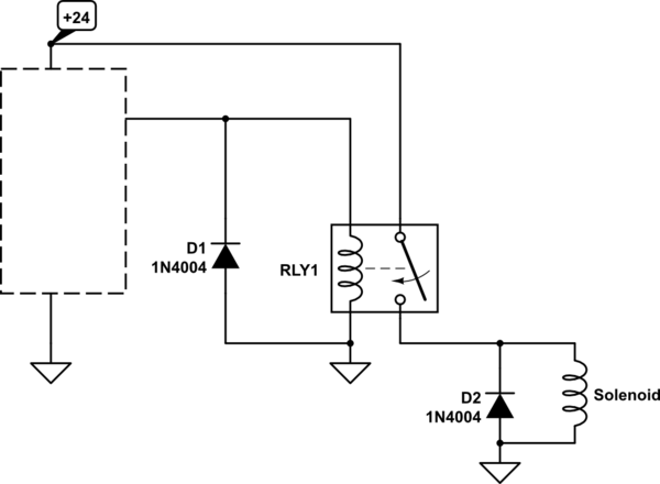
Just about any power relay with 5A-10A rating will work, probably with a lifetime of many hundreds of thousands, perhaps millions, of operations, but you should put a diode across the solenoid coil so that the relay contact does not arc excessively when the contacts open.

Make sure the diode is connected correctly (reverse-biased) or you will probably damage the relay and the diode. A 1N4004 will work fine for this application.

You could also use a DC-output SSR if you wanted to avoid a mechanical relay- you would typically still need the diode.

schematic

simulate this circuit – Schematic created using CircuitLab

\$\endgroup\$
6
  • 1
    \$\begingroup\$ If it's not a SS relay I'd put diodes on both sides. He does not want to risk blowing up that sensor either. It does not look cheap. \$\endgroup\$
    – Trevor_G
    Commented Apr 6, 2017 at 3:23
  • \$\begingroup\$ As @Trevor says, you will need a diode across the relay coil if it's a mechanical type. If you use a PCB module as Tony suggests it may have a diode and drive transistor (and even an optoisolator) on there already. \$\endgroup\$ Commented Apr 6, 2017 at 3:24
  • \$\begingroup\$ Does the signal voltage from the sensor come in to consideration at all? @SpehroPefhany \$\endgroup\$
    – Seano
    Commented Apr 6, 2017 at 3:38
  • \$\begingroup\$ @Seano If your supply voltage is 24VDC it can drive a 24VDC coil relay directly, up to 100mA. A typical power relay as I suggest might be 1-2W for the coil, so that is plenty. \$\endgroup\$ Commented Apr 6, 2017 at 4:55
  • 1
    \$\begingroup\$ @SpehroPefhany Thanks for your help! So just to confirm, the relay would be connected to a constant power supply of 24 Vdc as well as to the output of the sensor to energise the coil? Just making sure my heads fully around this. \$\endgroup\$
    – Seano
    Commented Apr 7, 2017 at 0:26
1
\$\begingroup\$

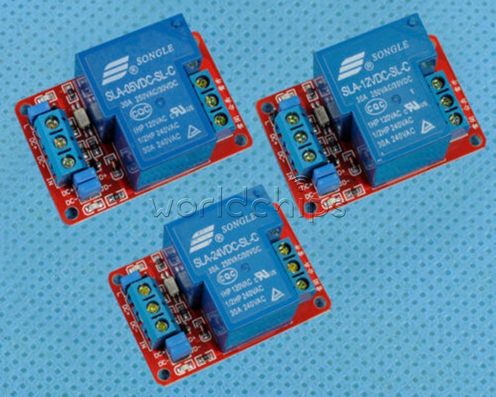
VA of 25 is only 1+ Amp at 24V but considering turn off arc, I would use 5A non gold plated contacts using an optoisolator driving 10mA from 3V (e.g. some require selection of series R for preferred IR current. ) with decoupling cap on 24V supply on Relay board for EMI reduction.

These are cheap (2$) and optoisolated as well in 5,12,24V types with many current ratings.

I suggest a 5A Relay but photo shows 25A ($2 on ee bae )

enter image description here

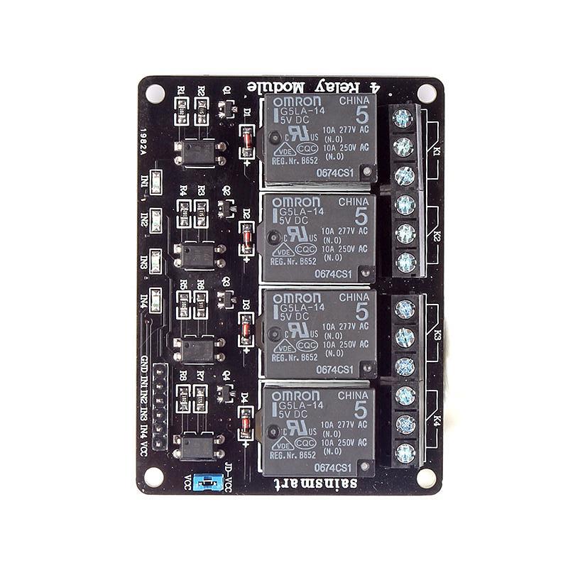
Or this multichannel one for future expansion/

It is not a 3V sensor but 5V.

THe sensor is 5V PNP <100mA pullup compatible with 5V Opto drivers for 15~20mA for high side drive with built in R on Relay cards that are PNP or NPN compatible.

http://www.ebay.ca/itm/OMRON-4-Channel-5V-Relay-Module-Opto-couple-For-Arduino-UNO-Mega-R3-AVR-ARM-/301286279825?hash=item46260fca91:g:RIsAAOSwgkRVVBzK

This one is better with many sources to buy.

enter image description here

Use suitable twisted pair for all drive pairs for improved EMI control. OMRON makes high quality relays.

Reverse diode clamp across output contacts are necessary to prevent high voltage impulse voltage with solenoid loads on turn off. (1N400x or equiv.)

\$\endgroup\$
3

Your Answer

By clicking “Post Your Answer”, you agree to our terms of service and acknowledge you have read our privacy policy.

Not the answer you're looking for? Browse other questions tagged or ask your own question.