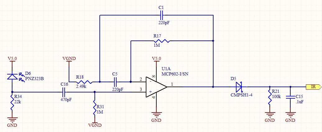
In addition to what others have said, I would point-out that your filter arrangement is suspicious. At first glance, the portion of the circuit from U1 pin 3 to U1 pin 1 looks like a typical second-order bandpass filter but instead of driving the left hand side of R18 and grounding the non-inverting input of U1, you are doing the opposite, ie using it in a non-inverting configuration.
In this configuration it is acting as a second order high-pass filter with a high frequency gain of 1 will have both low and high frequency gains of 1 (consider very high frequencies at which C1 & C5 are effectively short circuits, or at dc with the capacitors removed, and you will see a unity gain amplifier).
By my calculations, you have a centre frequency of 14.5kHz and a Q of 10 (ie a gain of 10 at 14.5kHz) at which the maximum gain of around 200 will be reached. By 32kHz, the gain is nearly back to 1 around 10 (and a gain of 400 will never be reached).
The calculations I have used are ....
Putting :- \$R=R_{18}\$ = 2.49k
\$C=C_1=C_5\$ = 220pF
\$k=\dfrac{R_{17}}{R_{18}}=401.6\$
I get :-
\$f_0 = \dfrac{1}{2\pi RC\sqrt k}\$ = 14.5 kHz and
\$G_{max} = \dfrac{1+k}{2}\$ = 201.3
Edit
To answer your question about 'k', it is commonly used to indicate a constant or a factor - in this case I have used it for the ratio of R17/R18. As you increase the ratio, you will get more gain at the centre frequency, but the centre frequency will decrease at the same time.
But before you go any further, consider what Tony Stewart said about ambient noise levels. Do you even need such a filter?
I would in any case avoid high Q active filters - they are just too sensitive to component tolerances. I would also avoid filters with very high passband gain for the same reason. If you do need a lot of out-of-band rejection, consider cascading separate lowpass and highpass filters. You might also consider using a phase-locked-loop (PLL) or digital filtering but we don't know what your operational environment is like.
If this is a personal project, and you want to experiment a little without using an receiver IC as stevenvh suggests, I would do the following. Firstly you want to convert the current from the photodiode into a voltage so R34 needs to be as large as possible. But this comes with some trade-offs. If your ambient light level (eg sunlight) gives you more than 150uA or so of diode current, you will starve the diode of bias and it's sensitivity will be reduced (ie it will saturate). So place your receiver in the brightest conditions it is likely to experience and measure the voltage at the junction of the diode and R34. If it is more than 3V or so you might have problems (depending on the diode) and you might thave to reduce R34. If you can view the waveform here with an oscilloscope, what happens as you increase the background lighting with your 32kHz signal present? If the signal amplitude doesn't reduce, you might be able to increase R34 to 100k say. Much higher than this and you might not see any further increase in signal due to capacitance.
An oscilloscope will also tell you how much extra gain you will need and whether out-of-band interference from artificial lighting, TV remotes etc requires you to filter the signal further.


 Report.