2
\$\begingroup\$

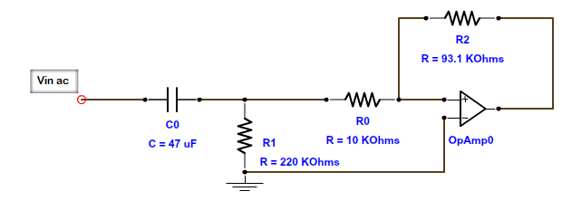
I am using a 47uF 10V SMD capacitor (GRM31CR61A476KE15L) mainly for DC blocking. But it make a phase shift on the signal, we can deal with this phase as long as it remain constant(hence the capacitance is constant too). Vin 50Hz maximum = 1.5V r.m.s , Dc offset= 0.5V After 60 days the performance of the circuit has degraded, the capacitance has been reduced to 35uF. By accident I have soldered it again and the capacitance return to 44uF (which is in the tolerance range +/- 10%). I read about this and found this page, talking about aging in high dielectric constant capacitors and the curing occur by temperature when soldering.
I really got shocked by this fact. So the question is how expert designer, design devices that could work for 10-15 years without degrade in performance with such phenomena?

\$\endgroup\$
6
  • \$\begingroup\$ That link shows variation, But very less (<5%) for aging for even 2000+ Hours. For 60 days - 1440 hours capacitance is 35uF (~25% reduction). This is not related to aging i guess. Did you considered DC characteristics of this capacitor. Are you really sure due to aging only Capacitance is reduced from 47uF to 35uF with in 60 days? \$\endgroup\$
    – user19579
    Commented Jun 5, 2017 at 6:08
  • \$\begingroup\$ how did you solder these ? within specs? Murata X5R's with C>10uF have a ~50 second time constant and a great deal of memory (double electric effect) how you measured it may affect accuracy of readings. Solder temperature can also affect barium Titanite crystal alignment and C value. X5R is not recommended as a stable RC filter time constant but great for supply decoupling due to many sensitivity factors include DC voltage. \$\endgroup\$
    – D.A.S.
    Commented Jun 5, 2017 at 6:34
  • \$\begingroup\$ @user19579, I checked the DC characteristics, it doesn't show any much variation in 0.5V. I am not sure it is due to aging, that is my guess. But it supported by the curing occurred after re-soldering. BTW the operating temperature of the device is about 40-50C \$\endgroup\$ Commented Jun 5, 2017 at 7:25
  • \$\begingroup\$ @TonyStewart.EEsince'75 , I used solder iron, temperature is 350C for ~1 second. I measured the capacitance immediately after soldering. But I installed the device in a calibration bench (which took more than 1 min at least), and the performance has changed. \$\endgroup\$ Commented Jun 5, 2017 at 7:27
  • \$\begingroup\$ Does this answer your question? Why does the capacitance value of an MLCC (capacitor) increase after heating? \$\endgroup\$ Commented Jul 21, 2022 at 18:43

1 Answer 1

1
\$\begingroup\$

You must pick your capacitor technology bearing in mind your intended use.

X5R (Or worse Y5V) is not really the smart choice for filters (Which is what you have if you care about phase shift thru the cap), apart from anything else you will have built a voltage controlled phase shift network as applied DC across that cap will cause SIGNIFICANT changes in value (This gets much worse with smaller case sizes).

C0G is generally ok for this sort of thing, but you will struggle with finding more then about 100nF or so. The other option is film or maybe a bipolar electrolytic (If going here make the value LARGE, so the phase shift is negligible over any reasonable amount of drift).

\$\endgroup\$
5
  • \$\begingroup\$ Could you please explain how the voltage controlled phase shift network work? And for electrolytic capacitor, will it maintain its capacitance for longer period? I know it is susceptible to dry-out \$\endgroup\$ Commented Jun 6, 2017 at 5:11
  • 1
    \$\begingroup\$ If you build an HP filter network with a cap that has significant variation with applied voltage (like say a small package Y5V will tend to) then changing the DC bias point will change the capacitance and thus vary the corner frequency and phase shift. \$\endgroup\$
    – Dan Mills
    Commented Jun 6, 2017 at 9:41
  • 1
    \$\begingroup\$ The usual trick for a DC removal filter where phase matters is to make the corner frequency very much lower then the lowest frequency of interest and thus minimise the effect on the phase of component drift. It is not that electrolytics do not drift, it is that you can get very long time constants so as to put the corner suitably low, if you make the corner frequency 1% of the lowest frequency of interest then a 10% change in capacitance is a very small phase shift. \$\endgroup\$
    – Dan Mills
    Commented Jun 6, 2017 at 9:42
  • 1
    \$\begingroup\$ Another option would be an opamp integrator wrapped around your input amp to cancel the DC, use a megaohm or so of resistor with a good quality film or tantalum cap, and a jfet opamp. This effectively forms a capacitor multiplier allowing the use of a large C0G wile still giving a usefully low corner frequency. \$\endgroup\$
    – Dan Mills
    Commented Jun 6, 2017 at 9:44
  • \$\begingroup\$ The corner frequency of this circuit is 0.33Hz but I had another circuit almost the same configuration and affect the whole performance has a corner frequency of 2Hz. I will solve it by this method, thank you! \$\endgroup\$ Commented Jun 6, 2017 at 11:33

Your Answer

By clicking “Post Your Answer”, you agree to our terms of service and acknowledge you have read our privacy policy.

Not the answer you're looking for? Browse other questions tagged or ask your own question.