1
\$\begingroup\$

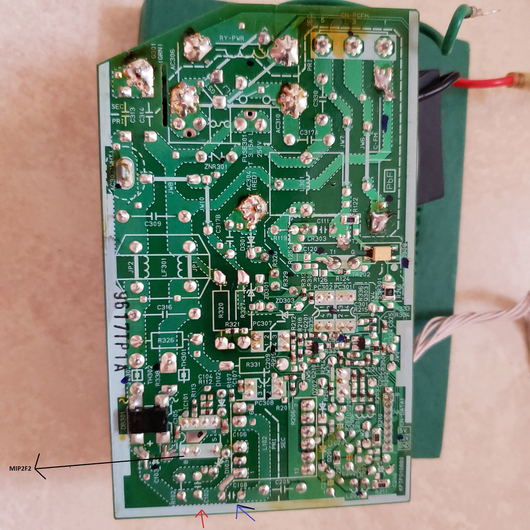
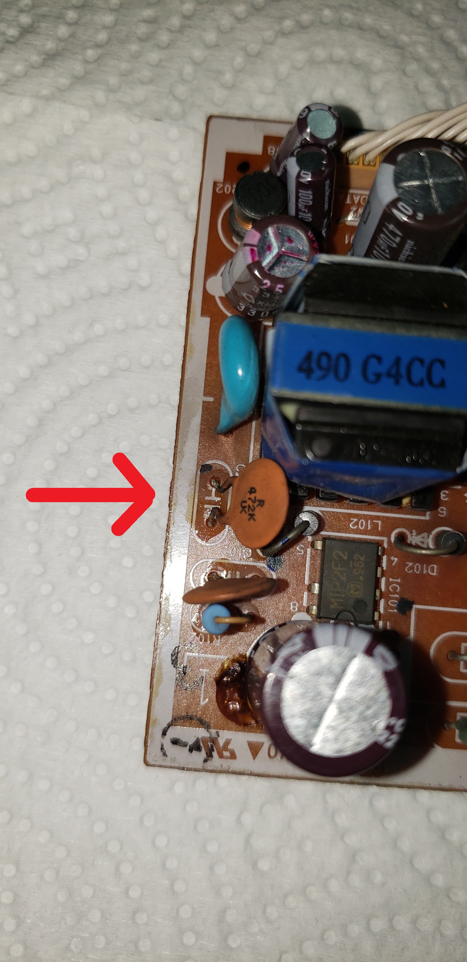
I'm trying to replace this low value ceramic capacitor marked R472KUK.

I figured out it's a 4.7nf (4700pf) with 10% tolerance.

What's the "R" at the beginning of its code? What does the "UK" in the last line mean?

Voltage I guess would be like upto 500V.

That capacitor is close to a MIP2F2, so I believe is to suppress noise.

enter image description here

enter image description here

\$\endgroup\$
8
  • \$\begingroup\$ Don't guess as to voltage ratings; it could be 500 V or it could be 20 V. This doesn't appear to be the marking code I'm familiar with, and a cursory search doesn't find any that do match. I'm not sure it'll be possible to determine the voltage ratingwithout knowing the manufacturer. \$\endgroup\$
    – Hearth
    Commented Jun 30 at 22:40
  • \$\begingroup\$ That's all the information i currently have, so what to do now? Say I use a 500v with the given capacitance, will it good? MIP2F2 is an oscillator / switching IC. \$\endgroup\$
    – Panamanian
    Commented Jun 30 at 22:45
  • \$\begingroup\$ If you put 500 V across that capacitor, there's a chance it'll work fine, a chance it'll immediately explode, and worst of all, a chance it'll work for a while and then just stop working at some unknown future time when it's impractical to get to it to replace it. \$\endgroup\$
    – Hearth
    Commented Jun 30 at 23:00
  • \$\begingroup\$ --And now I see that you're trying to replace the capacitor, not determine its ratings for use in a different project. Show us a schematic, and in particular tell us what the highest voltage involved in the circuit is. \$\endgroup\$
    – Hearth
    Commented Jun 30 at 23:01
  • 1
    \$\begingroup\$ It's not even UK, it's labeled U< which may be a manufacturer specific ID or date or lot code but also could define the voltage. The problem is, the cap looks perfectly fine and ceramic caps rarely degrade or go faulty so there should be no reason to be replacing it anyway. It looks like it's a part of a RCD snubber, so all the cap parameters, other than just the capacitance and voltage, are highly important. \$\endgroup\$
    – Justme
    Commented Jul 1 at 4:42

2 Answers 2

5
\$\begingroup\$

Since you state you're just trying to replace it, look at the highest voltage rating on any marked component on the board, and go with that rating.

The physical size of the capacitor is a clue -- if the substitute cap is the same diameter or larger, it should be fine (actually, the thickness is a better clue, but harder to judge.).

That said, 4.7 nF ceramic caps are inexpensive at any voltage, and a mistake picking a higher-rated cap would cost little more and have no negative consequences -- as long as it fits.

\$\endgroup\$
5
\$\begingroup\$

Identification

Follow the traces, from the capacitor in question, to the main filter cap (electrolytic type) of a AC-DC converter, which it is connected across. It therefore sees peak rectified mains voltage, say 160 or 320V. A 500V type would be a fine replacement, perhaps in X7R or Y5P.

Ceramic capacitors are unlikely to fail, and the purpose of this part is fairly dubious already (many comparable circuits ably rely on the electrolytic alone). It will have a modest EMI impact, which it's unlikely you are testing for (this requires specialized equipment), so it's uncertain what you expect to gain by replacing it -- if the power supply is completely dead, your concern lies with other components.

Incidentally, it might not be nominal value. This still isn't justification to replace it, but it is worth understanding when diagnosing capacitors of this type (or salvaging, as the case may be). Type 2 dielectric ceramics age over time: the value goes as 1/log(time), more or less. A nominal 472K = 4.7nF 20% type (probably Y5P dielectric) might reduce by half or so after some decades time, whether sitting around or in active use. Aging is reversed by annealing the ceramic above its Curie temperature -- basically, aging is reset upon soldering, which reaches high enough temperature (for most type 2 ceramics) for this to occur.

An illustration: a random, I think 103Z disc from my junk box:

enter image description here
Source: my website, https://www.seventransistorlabs.com/Images/Z5U_CV_Plot.png

The blue curve was a part having sat in a tray for -- probably more than two decades now? I've got some old bits of salvage floating around. The red curve is the same part, after having annealed it by holding each lead at soldering temperature for 10 seconds.

Notice the axis plotting against bias voltage: these types are sensitive to voltage, and it's likely your part is decreased to a small fraction of its rating in operation (at 100s of V). The slope varies between types, values and ratings (consider the voltage applied over the thickness of the ceramic disc itself), this curve will not be proportional to the part in question -- but a similar curve, rescaled, likely applies.

The regulator by the way, is possibly Panasonic MIP2F20MSSCF; I don't see a datasheet offhand, but the MIP2F20MTSCF seems very similar.

Repair

A likely repair strategy is concerned with main power components: fuses, rectifiers, capacitors, regulators and controllers. Also consider likely cascade failures, e.g. shorted output --> output rectifier fails --> primary regulator fails --> fuse blows. You may need to replace many components, which makes board-level servicing much more promising in most cases. (Given appearances, I'm guessing this is vintage equipment that might not have spares available, or economically so, encouraging component-level servicing.)

\$\endgroup\$
1
  • \$\begingroup\$ Thanks Tim for your complete answer. \$\endgroup\$
    – Panamanian
    Commented Jul 1 at 5:53

Your Answer

By clicking “Post Your Answer”, you agree to our terms of service and acknowledge you have read our privacy policy.

Not the answer you're looking for? Browse other questions tagged or ask your own question.