0
\$\begingroup\$

I have a PIC18F14K50 with a Microchip PICKit2 and the development board pictured below:
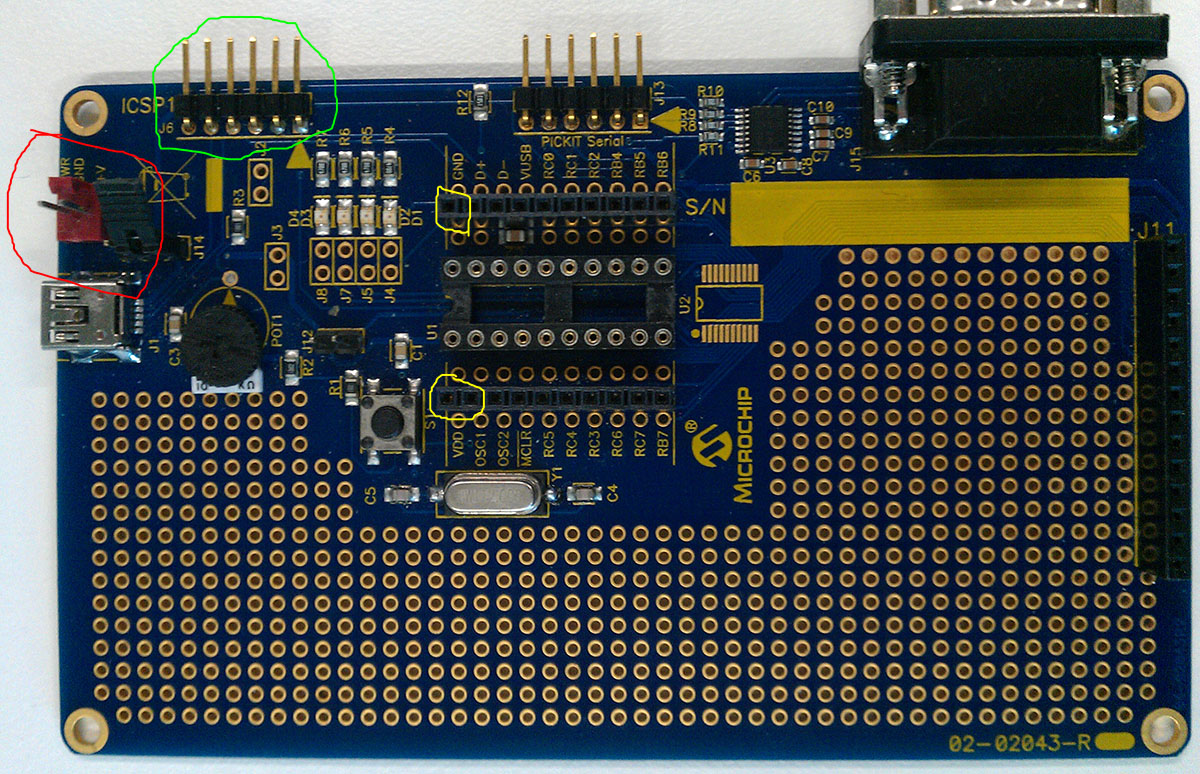
Microchip Development Board

Up until now, I've been using the board only for programming using the power supplied by the USB/PICKit, however now I need to use the board a little more permanently as I'm using 12Mhz at 4x for USB and my breadboard has some issues at those frequencies.

I can put my IO Expanders and other supporting components onto this board, however I need external power (5V) to drive everything. USB doesn't supply enough current to run my whole setup.

I originally supplied my +5V to pin 1 circled in yellow, and GND to pin 20 also circled in yellow. When I connected my PICKit to the ICSP1 (green circle), it burnt out my PICKit. I have since bought a new PICKit but I need this external power working.

I noticed the red power header, circled in red. I imagine these are just direct connections to pins 1 and 20 on the MCU, so I'm not sure how these would be any different to supplying power to the yellow circles.

How/where should I be connecting my external +5V such that it doesn't blow my PICKit? Thanks.

\$\endgroup\$
1
  • 2
    \$\begingroup\$ Surely the documentation that comes with this board tells you all this. If there is a jack for power, and it looks like there is, that is the obvious place to connect power. Look in the documentation or at least the schematic to see what kind of power this board wants at that jack. Microchip often powers their stuff from 9 V, but I don't see their usual wall wart socket on this board. Again, see the documentation. \$\endgroup\$ Commented May 2, 2012 at 23:52

1 Answer 1

2
\$\begingroup\$

It appears you are using the "Low Pin Count USB Development Kit", part # DV164126.

As long as pins 1 and 2 of J14 are jumpered together, then pin 1 of J9 is connected to pin 1 of the micro (Vdd) and pin 2 of J9 is connected to pin 20 of the micro (Vss). So powering the board of J9 should work fine.

You also want to leave off the jumper on J12 since you don't want the +5 from Vbus (pin 1 of the USB socket) also trying to power the board.

As far as blowing up your PICkit2, I believe when you connect to the PICkit from the MPLAB IDE it asks whether the board is 3.3v or 5v. Make sure you are selecting 5v. Otherwise I don't see why the PICkit would have an issue working with the development board, assuming you are plugging it into the ICSP1 header correctly.

\$\endgroup\$

Your Answer

By clicking “Post Your Answer”, you agree to our terms of service and acknowledge you have read our privacy policy.

Not the answer you're looking for? Browse other questions tagged or ask your own question.