1
\$\begingroup\$

I'm working on a project where I need a transistor. I want a Attiny85 mcu to turn of and on a relay. But the current in that chip is to low so I figured out I have to use a 2N2222 NPN transistor as a switch so the relay could draw current from the source and not thru the mcu.

I'm using the tool over at http://www.falstad.com/circuit to help me set up the circuit, but I'm having some problems.

To understand NPN transistors I've tried to take the example at falstad and update it to my settings, using 5V for power, adding a switch. But it does not work. I really want to test it before I get to solder it together so the tool was really nice.

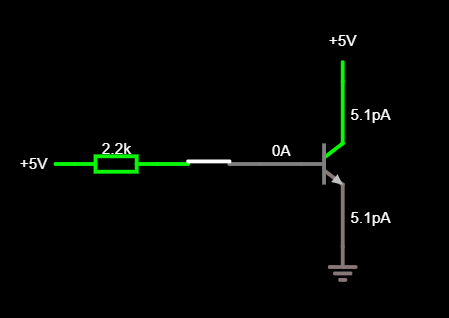
enter image description here

\$\endgroup\$
5
  • 1
    \$\begingroup\$ It won't work as you want without a relay coil. They're not telepathic, they need coil current to operate. \$\endgroup\$
    – Andy aka
    Commented Jul 20, 2017 at 7:51
  • 1
    \$\begingroup\$ Related: electronics.stackexchange.com/a/25676/35022 \$\endgroup\$
    – MarkU
    Commented Jul 20, 2017 at 7:53
  • 1
    \$\begingroup\$ Possible duplicate of Driving a relay directly with a microcontroller? \$\endgroup\$ Commented Jul 20, 2017 at 8:09
  • 1
    \$\begingroup\$ Very basic rule - to turn on an NPN raise the gate voltage more than 0.6V above the emitter voltage, usually through a resistor like you already have. BTW, in the above diagram you would burn it out instantly. Put the load in the collector side \$\endgroup\$ Commented Jul 20, 2017 at 8:49
  • 1
    \$\begingroup\$ Also, do not forget the protection diode across the relay coil \$\endgroup\$ Commented Jul 20, 2017 at 8:50

1 Answer 1

2
\$\begingroup\$

You've made a mistake when using your falstad simulation.

In the top right corner is a 'Run/Stop' box. What I suspect has happened is that you've taken the NPN transistor example. Changed the voltage to 5V without adding a base resistor first, exceeded the max current which has caused the simulation to stop.

enter image description here

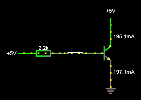
If you press the 'Run/Stop' button again now that you've added your base resistor then it should simulate correctly. As a general rule to remember, if there are no yellow dots (which represent current flow) then your simulation has most likely stopped.

enter image description here

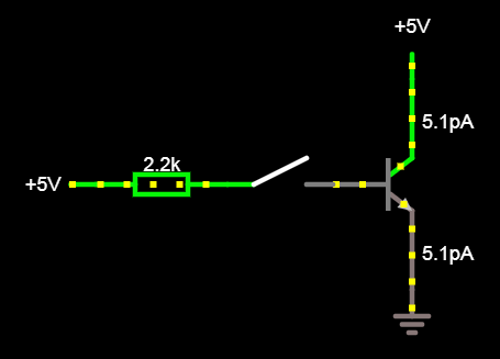
Edit: Just for completeness, here's the current flowing through the transistor with no voltage on the base, notice how the current values are the same as your image?

enter image description here

\$\endgroup\$

Your Answer

By clicking “Post Your Answer”, you agree to our terms of service and acknowledge you have read our privacy policy.

Not the answer you're looking for? Browse other questions tagged or ask your own question.