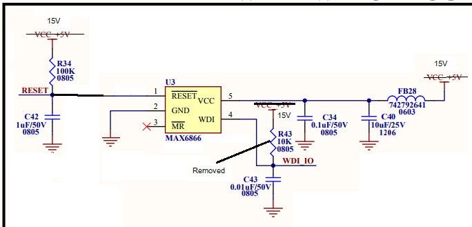
In below Design , working ok with Vcc was 5V, but due to some modification I have only 15V power supply available to use this circuit. So i change as per 15V requirement ( see below image), Pin 1 is open Drain so did not removed R34 Removed R43 WDI_IO is drive form micro controller Reset of Pin 1 goes to Trigger input of 555 IC ( which has max working voltage of 18V , not shown in SCH)
Since U3 max voltage range is 5.5V , So I am thinking to change FB28 with 1K resistor and C40 with 5.0V Zener Diode.
Zener Spec:- 5.0Vz, Test Current 5mA Max PD 500mW So Max current = 500mW/5V = 100mA Min Rs = (15V-5V)/100mA = 100oHM
I choose 1K as Series Resistor so Current will be
I= (15-5)/1K= 10mA, This can supply both zener and load whch is my IC I as per data sheet IC Current suppy need in approx 200nA).
Does this look ok ,to use zener in this case as my load current in not much.

