2
\$\begingroup\$

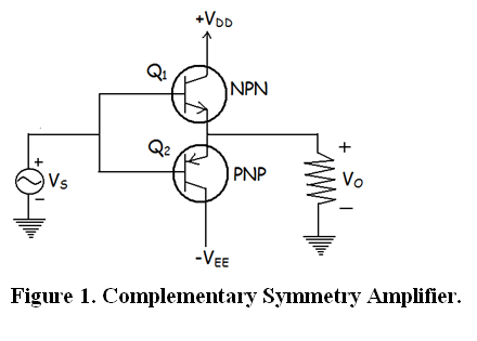
I'm working on a 4MHz HF power amplifier (Very simple) and was wondering why people still use bipolar transistors for class B amplifiers?

Do they have better linear current gain etc. vs a FET? Is it because you only need 0.7V above the emitter to conduct so there is minimal crossover distortion (logic level FET could help this)? Is it because "it is how it has been done forever?"

Most of my experience is with Class D and up style amplifiers. Where I mostly just care about operating as a switch and ignore any linear effects.

enter image description here

\$\endgroup\$
5
  • \$\begingroup\$ Valid point with the current vs voltage controlled devices. I guess I didn't think about it very hard before posting the question. \$\endgroup\$
    – MadHatter
    Commented Aug 7, 2017 at 2:35
  • \$\begingroup\$ If you are talking about BJY's used in an RF amplifier....they are Class C and rarely in a complimentary configuration: home.sandiego.edu/~ekim/e194rfs01/lec24ek.pdf \$\endgroup\$ Commented Aug 7, 2017 at 4:21
  • 1
    \$\begingroup\$ The document: k5tra.net/tech%20library/Motorola%20app%20notes/… answers most of your questions. \$\endgroup\$
    – glen_geek
    Commented Aug 7, 2017 at 4:28
  • \$\begingroup\$ @glen_geek Dagnabbit! I see "CHART NOT AVAILABLE ELECTRONICALLY" right where I wanted to see a Smith chart!! \$\endgroup\$
    – jonk
    Commented Aug 7, 2017 at 4:35
  • \$\begingroup\$ Try embedding a proper RF circuit into your question or provide a link to one. The push-pull circuit is meaningless and provides zero relevant context. \$\endgroup\$
    – Andy aka
    Commented Aug 7, 2017 at 7:21

1 Answer 1

2
\$\begingroup\$

Well.. one is current controlled and the other is voltage controlled.


Another point to make is that it's very easy to open a BJT half-ish, with a MOSFET you got an equation that looks a little bit like this: \$I_{DS}=K×(V_{GS}-V_{TH})^2\$. There's a square in there. For the BJT it's just \$I_{CE}=I_{BE}×\beta\$ (in saturated region). For the MOSFET it means that when the sound goes up, on the output you get the square of that... which is not really what you want, you want to linearly amplify the sound, like the BJT does.

You want this \$Y=K×X\$, not \$Y=K×X^2\$

If you however use some feedback then you can make it linear... like using an op-amp. Most modern op-amps, especially those of modest specifications, will be MOSFET-based, if you just make a feedback with resistors then the amplification will be linear, which is what you want, and then it will work nearly identical to the class B amplifier.


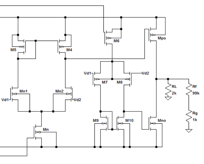
This is the schematic of some MOSFET based op-amp. It's too much hassle needed to linearize a class B amplifier.
enter image description here

But as you can see, the \$M_{PO}\$ and \$M_{no}\$ forms a class B amplifier stage, there's just so much fuzz in the foreground to linearize it. For an op-amp where everything is in a small package, no problem. All the transistors receive roughly the same \$K\$ since it's all in one batch. If you however need to use all the individual components in packages then there will be some mismatch with the \$K\$'s (in the equation above) because the components were all made in different batches. With different \$K\$ in the above equations, everything will be... mismatched and you'll end up with a dysfunctional op-amp which will make your class B amplifier dysfunctional.

\$\endgroup\$
5
  • 1
    \$\begingroup\$ "Any modern op-amp will be MOSFET based" -- I beg to differ on this one -- bipolar op-amps are still a thing for a variety of applications, and for good reason too. \$\endgroup\$ Commented Aug 7, 2017 at 3:08
  • 1
    \$\begingroup\$ "Well.. one is current controlled and the other is voltage controlled." - That is not strictly correct. BJTs are voltage controlled but they do have a significant base current. It is just convenient that the ratio of the base current to collector current is fairly constant. \$\endgroup\$ Commented Aug 7, 2017 at 3:16
  • 2
    \$\begingroup\$ The Ebers-Moll equations for how a transistor operates are based on the base emitter voltage, not the current. The operation of a MOSFET are also based on the gate to source voltage. \$\endgroup\$ Commented Aug 7, 2017 at 3:24
  • \$\begingroup\$ So technically it's saying that the current flowing through a diode is based on the voltage. Okay, you got me there. Fruitless. \$\endgroup\$ Commented Aug 7, 2017 at 3:28
  • 1
    \$\begingroup\$ Both the mosfet and the BJT use gm in their small signal linearized models. For good reason. Just curious. How would you explain the behavior of a BJT current mirror? As Einstein is quoted as saying, “Make things as simple as possible, but not simpler.” I think @KevinWhite was just keeping the correct things out in plain view where they belong. I would have done the same, had he not. \$\endgroup\$
    – jonk
    Commented Aug 7, 2017 at 4:30

Your Answer

By clicking “Post Your Answer”, you agree to our terms of service and acknowledge you have read our privacy policy.

Not the answer you're looking for? Browse other questions tagged or ask your own question.