2
\$\begingroup\$

I am trying to make a very compact and lightweight circuit that will cause an IR LED to blink on and off at a constant rate, preferably at least once per second but the flashes can be more spaced out. Due to weight constraints, I would like to use a 3V coin battery to power the circuit. The battery doesn't need to last a long time because it can be easily replaced. I have looked online at LED pulse circuits but I haven't been able to find any that work at 3V. Does anyone know of a way to either reduce the voltage of some pulse circuits by reducing the resistance or a way to make a low resistance pulse circuit? Thank you very much in advance!

Here's a link to one design I have looked at http://www.instructables.com/id/How-to-Make-an-Led-Pulse-Circuit/

\$\endgroup\$
5
  • \$\begingroup\$ That circuit will work with almost any voltage. You just need to play with the values of the resistors (and maybe the capacitors). Maybe try replacing the resistors with potentiometers so you can adjust the resistance until it works. A multimeter will be a must. \$\endgroup\$ Commented Aug 10, 2017 at 3:11
  • \$\begingroup\$ If the circuits your looking ate have an op amp that has a minumum voltage range lower than 3v you should be able to use them. Most charging cap circuits will also not be affected by a different Vcc \$\endgroup\$
    – Voltage Spike
    Commented Aug 10, 2017 at 4:03
  • \$\begingroup\$ The instructable design is useless for 3V but ok for 9V. You can use a 3V CMOS 74ALCV14 Schmitt Trigger to make a 1 Hz Clock and discharge current with a pulse from a Cap, but dont expect more than a few mA averaged due to the coin Cell ESR charge rate to the Cap. SO drive the IR LED thru a cap using a large cap across the coin cell and using the C ratio to determine the peak/avg ratio roughly and use a Schottky diode reversed across the IR LED or two back to front in parallel to use both edges. with 1.2~1.3V across the IR LED for each pulse. \$\endgroup\$
    – D.A.S.
    Commented Aug 10, 2017 at 4:39
  • \$\begingroup\$ Series Cap may be around 350uF. Shunt Cap on Coin cell will be bigger than coin cell. so consider the thickest coin cell you can get instead. e.g. 1cm or more.!! You cant squeeze more joules out of a tiny coin cell with a boost converter. \$\endgroup\$
    – D.A.S.
    Commented Aug 10, 2017 at 4:54
  • \$\begingroup\$ Depending on what you can accept as the pulse width (unstated so far), you could probably get almost a year out of a CR2032 at the pulse rate you are talking about. But probably not with the instructables circuit, which uses a very nice (simple) PUJT relaxation oscillator but wastes some current in the voltage divider that sets the trigger point for the PUJT. Are you trying to talk to bugs with this? Or what? \$\endgroup\$
    – jonk
    Commented Aug 10, 2017 at 6:42

5 Answers 5

1
\$\begingroup\$

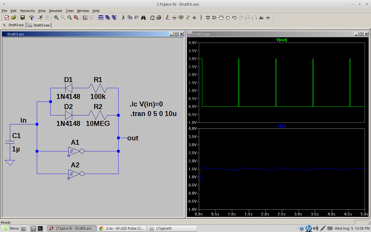
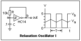
Not boost converter nor Op Amps, but low RdsOn CMOS Logic Relaxation Oscillator with a Schmitt Trigger. enter image description here

but DON'T use a HC14 , it has too high an output ESR @3V and use 10M 0.1uF for 0.5s ramp ( due to 1/3Vdd= Va=1V not ~60%=T)

BOM

This should last a few days.

\$\endgroup\$
1
\$\begingroup\$

Here's another answer. Same type of oscillator as Tony Stewart's but I assume you want very short ON pulses (like a flash) every second or so.

This is accomplished by using steering diodes D1 and D2 to route the charge and discharge current through different resistors so that the duty-cycle can be easily adjusted by the value of R1 and R2. Because R2 is 100x R1, the on time is 1/100 or 1% of the period.

Schmitt Oscillator with narrow duty cycle

You can use a chip like TI SN74LVC2G14. It can run as low as 1.65 Volts. At 3 Volts, it can drive 24 mA per inverter. By using two in parallel, you can drive 48 mA. You would, of course, need to add a series resistor to the out pin and then your IR LED.

http://www.ti.com/product/SN74LVC2G14

\$\endgroup\$
6
  • \$\begingroup\$ High to turn on? \$\endgroup\$
    – Jason Han
    Commented Aug 10, 2017 at 6:05
  • \$\begingroup\$ What do you mean "High to turn on"? It's an oscillator. You apply power and it starts oscillating. \$\endgroup\$ Commented Aug 10, 2017 at 6:08
  • \$\begingroup\$ How would you connect the IR led? \$\endgroup\$
    – Jason Han
    Commented Aug 10, 2017 at 6:08
  • \$\begingroup\$ Oh, I thought it was pretty obvious. Use the "out" net, connect to a series resistor to limit the LED current, resistor connects to the LED anode, LED cathode to GND. \$\endgroup\$ Commented Aug 10, 2017 at 6:26
  • \$\begingroup\$ What is the resistor value if I want to drive 48mA into a VF 1.5V LED? \$\endgroup\$
    – Jason Han
    Commented Aug 10, 2017 at 6:42
1
\$\begingroup\$

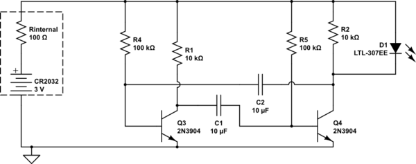
An astable multivibrator like this should work.

schematic

simulate this circuit – Schematic created using CircuitLab

Note R2 parallel with the LED this makes the voltage swing on Q4 collector sufficient to drive Q3

\$\endgroup\$
1
  • \$\begingroup\$ I tried this circuit on a breadboard, but i didn't get the blinking light, only a constant light up... \$\endgroup\$
    – user188171
    Commented Jun 26, 2018 at 13:05
1
\$\begingroup\$

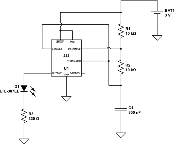
The circuit link used by you is purely resistive and very much power hungry. You can use a low power version of 555 timer in astable mode to make 3v or lower voltage LED pulse circuit. TLC555, LMC55, TPL5010 are low power version of timer IC. Apart from being low power you'll be able to get power efficiency and longer battery life.

Refer this circuit for operating the circuit in astable (square wave) mode. Only difference will be using low power version of 555 time IC. You can change the pulse period by changing the value of R1.

schematic

simulate this circuit – Schematic created using CircuitLab

\$\endgroup\$
0
\$\begingroup\$

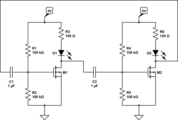
You can use this circuit below. Take note your allowable current is 50mA, IR LED must be low forward voltage type since you're only using 3V. The mosfet must also be low signal voltage type: https://www.vishay.com/docs/71172/si1032r.pdf

schematic

simulate this circuit – Schematic created using CircuitLab

In the beginning when 3V supply is not available, both M1 and M2 gate are 0V. When 3V3 is available, M2 will turn on first as surge current flow is higher in R3 as compare to R6. D2 will then light up. (DC current will not go thru C2, instantaneous current will.)

M2 close will discharge C1 and the R1 + R2 circuit have to start charge up to 1.5V again (at M1 gate). When the voltage reaches suitable VGS of M1, M1 will close and causes M2 VGS to go low; causing M2 to open. D1 will then light up and D2 off.

You may play around R1, R2, C1, R4, R5 and C2 for the timings. If only 1 LED is needed, replace them (R3 + D1) with a suitable bigger resistor.

\$\endgroup\$

Your Answer

By clicking “Post Your Answer”, you agree to our terms of service and acknowledge you have read our privacy policy.

Not the answer you're looking for? Browse other questions tagged or ask your own question.