What kind of IR detector and converter circuit could be used to down-convert an IR remote signal (in the neighborhood of 35 to 45 kHz) into audio frequency signals (0.1-20 kHz) of the appropriate level and drive to feed the mic input on a mobile phone TRRS headset jack for further analysis and decoding? Would something simply involving a divide-by-4 cascade of two D flops work? Or would decoder/(re)encoder chips or a microcontroller chip be necessary?
3 Answers
This is a no-brainer really.
The 36kHz is the carrier frequency, the baseband signal is well within the audio range. Use an integrated RC receiver, it would be silly to make your own. They combine AGC, bandpass filter and demodulator.
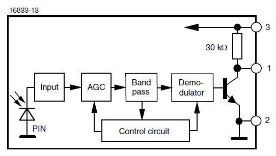
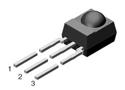
I've used Vishay devices, and I'm quite satisfied with them.
There's a number of protocols, but RC-5 is the most used, so I'll take that as an example. RC-5 uses Manchester coding, with a bit time of 1.778ms, so that the lowest frequencies are 281Hz and 562Hz resp.
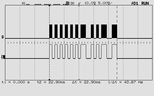
That's well within the audio band, including quite some harmonics, so low-pass filtering it at 20kHz, or even 10, doesn't harm the signal's integrity, and you'll be able to detect edges. The image shows an 889\$\mu\$s pulse plus ditto pause, giving the higher frequency of 562Hz, cut off at 10kHz.
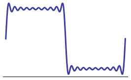
Mobile phone voice bandwidth is limited to 4kHz, however, and since the microphone input is primarily meant for voice input that limit may apply already here. You can play MP3 quality audio with it, but I don't know if you can record it as well. Anyway, with a worst case brick wall filter at 4kHz that same signal will look like this:
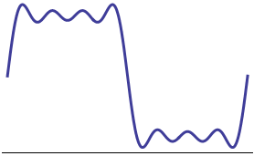
Still no problem; you can easily pass the signal through a comparator when sampling and you'll get perfectly timed edges.
That's it really. Connect the output of the RC receiver to your phone via a resistor divider to bring the logic level signal down to mic level. If your receiver works at 3.3V the output level will be about 60dB above 2mV RMS microphone level. In that case use a 70k\$\Omega\$ resistor (for a total of 100k\$\Omega\$, the pull-up in the receiver is already 30k\$\Omega\$) in series with a 100\$\Omega\$ resistor to scale the RC signal down. YMMV.
trivia
The 14 bits commands repeat with 50 bit time pauses for a total period of 64 bit times, so that the repetition frequency is around 9Hz. The baseband signal is sometimes used directly to blink a visible light LED.
I still find this question confusing. Do you want the frequency of the carrier in the IR signal to map into some property of the generated audio signal?
If yes (and it would be hard to imagine what you would need that for), tell us. For that, you need a circuit quite more complex than just an integrated IR receiver.
If no (so, you just want to decode IR signals using the mic input of any device, and you don't need that mapping), just use an integrated IR receiver, such as a Sharp GP1UX310QS, connect a pull-down resistor from its output to ground (to form, together with its internal \$100\;k\Omega\$ pull-up resistor, a resistor divider, that will bring its output voltage (in the order of 3 V) down to an appropriate level for your mic input -with a max amplitude in the range 10 mV to 150 mV, depending on the sensitivity), and finally connect the output also to the mic input. For instance, RC-5 encoding will give you Manchester-encoded bursts with a frequency between 281 Hz and 562 Hz (which lie inside the audio band), repeated with a frequency of 8.8 Hz (which does not lie in the audio band, but it doesn't matter, because you will still be able to see the 281 Hz to 562 Hz bursts), and which can be sampled and decoded by your phone (assuming that the frequency response of your mic input goes down to 281 Hz, which might not be the case).
About the pull-down resistor: since the optimal value for it depends on the input impedance of your mic input, and you haven't provided that data, best is to use a small, adjustable resistor. Connect one end of it to the output of the GP1UX31QS, the other end to ground, and the wiper to your mic input. A \$10\;k\Omega\$ or \$20\;k\Omega\$ adjustable resistor will probably be fine.
How I computed the frequencies:
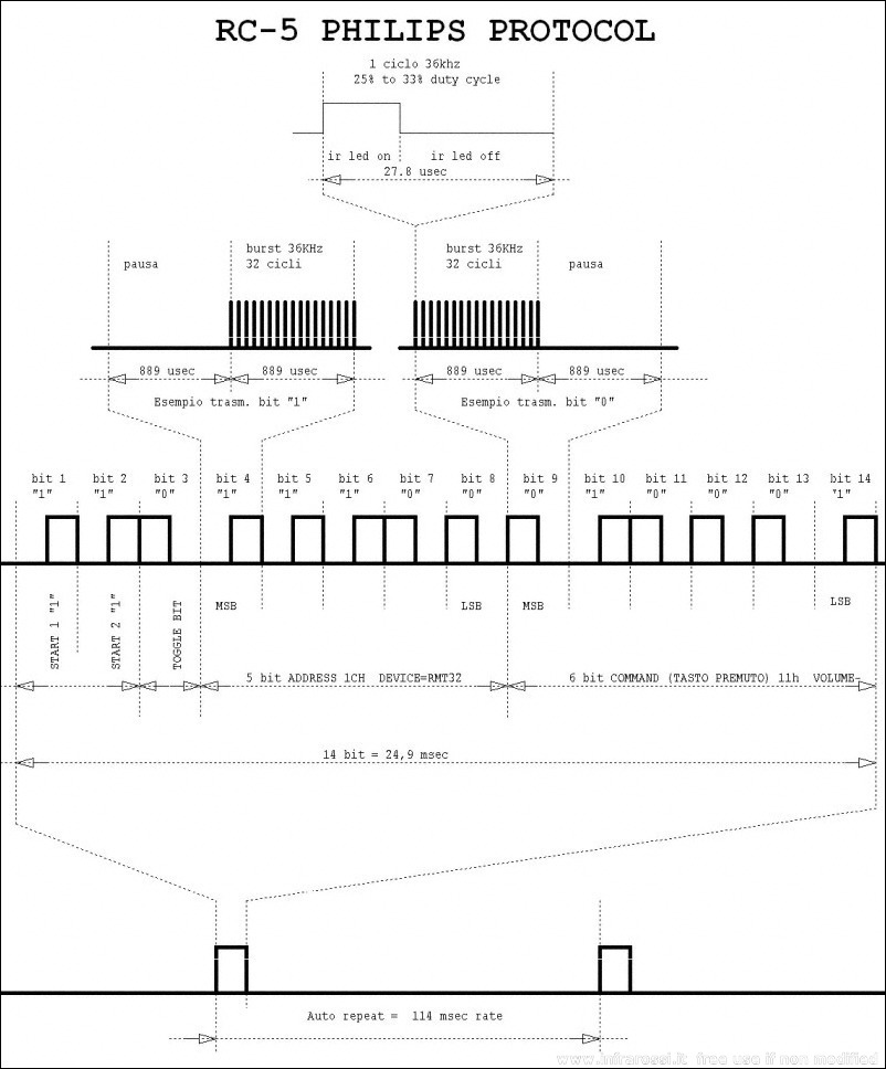
Notice that 889 us is the duration of half a bit.
During intervals in which the bits encoded are all equal, like 0000 or 1111, the frequency will be
\$f_1=\dfrac{1}{2·889\;\mu s}=562\;Hz\$.
During intervals in which the bits encoded are alternating, like 0101, the frequency will be
\$f_2=\dfrac{1}{4·889\;\mu s}=281\;Hz\$.
Also,
\$f_3=\dfrac{1}{114\;ms}=8.8\;Hz\$.
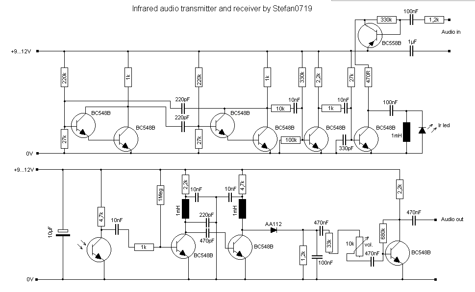
Update: This is not my design, but looks reasonable for 3m distance. More effort to get 10m. Credit to design in on schematic. Need Stereo? Need full specs before further comment.
Your solution that you requested needs a Trans-impedance amplifier for the detector, AGC amp, matched BPF Q>20, and linear very sensitive detector integrated into a low noise IR Receiver. Very inexpensive and reliable. I used the older version and using low noise V+ I got 30 meter range. Even bouncing off walls. Use 2 or 3 Sharp® emitters @ 75mA or more for best range.
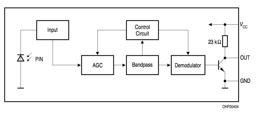
See bottom of page for both specs and app note.
After you understand how IR receivers work and understand FM SNR improvement ration improve SNR and low FM ratio of BW of carrier to Audio, it gets worse. Also AM BW vs SNR is an issue in this app—you realize this wont work. You cant easily fit high quality audio of 20kHz on a 40kHz carrier unless you start to investigate baseband modulation schemes like PSK. So consider the block diagram and try to see what you need to change to use PSK modulation where +/-180 would be worst case Pk-Pk.. AM schemes have path loss issues so you want to use AGC to compensate for wall reflections and use PSK. If you had say pushed the carrier up to 450kHz, then you could use AGC and filters used in AM radios, but then have a great difficulty with the transimpedance amplifier and diode capacitance vs load sensitivity.
May I ask, how far do you expect to go, and what quality you want? Cell phone? AM radio or FM quality? Stereo or Mono?
I think unless you are invested deep into baseband and FM demodulators, it might end up being a Make Buy decision, I would buy rather than re-invent the wheel using stereo 10kHz BW with FM at a higher carrier frequency.
-
\$\begingroup\$ I found one product intended for a room with a high power array of emitters for a room full of listeners... The Williams Sound WIR TX75 Infrared Transmitter shall consist of an all in one modulator and emitter operating on 2.3MHz and/or 2.8MHz. The carrier frequency shall use 50kHz deviation and 50µS pre-emphasis. (not cheap, just a baseline williamssound.com/catalog/wir-tx7518-sys).. another design runs . Operating in the higher 2 to 6 MHz on IR \$\endgroup\$– D.A.S.Commented May 26, 2012 at 1:00
-
\$\begingroup\$ Gibberish. As usual. -1 \$\endgroup\$ Commented May 26, 2012 at 12:00
-
1\$\begingroup\$ Can you please fix your typos and improve your sentences for clarity? You might have good info but the way you type it out is really difficult to read. \$\endgroup\$– dext0rbCommented May 28, 2012 at 17:17

