0
\$\begingroup\$

I understand that through varying voltage, data can be transmitted as "high" and "low". What I don't wrap my head around is how the receiving end "dissect" the frame.

I know there is a concept of frame, lets say the receiving end will always receive 8 bits at a time as one frame and begin the next frame for the next 8 bits.

1111 0000 -> one frame

But what if one bit is lost? Won't that create a domino effect for the rest of running time since frame will be offset by one bit and everything after will not be correct.

How does this get enforced on bit level?

\$\endgroup\$
11
  • 3
    \$\begingroup\$ You are forgetting about time... \$\endgroup\$
    – Trevor_G
    Commented Sep 11, 2017 at 20:39
  • \$\begingroup\$ Can you elaborate : ) \$\endgroup\$
    – Zanko
    Commented Sep 11, 2017 at 20:41
  • 4
    \$\begingroup\$ read about synchronous and asynchronous transmission. en.wikipedia.org/wiki/… \$\endgroup\$
    – Trevor_G
    Commented Sep 11, 2017 at 20:42
  • \$\begingroup\$ By measuring time accurately, and using the data received to correct for your view of time. Yes, its imprecise. That is why it takes several steps to increase the speed that things work reliably at. \$\endgroup\$ Commented Sep 11, 2017 at 20:51
  • 1
    \$\begingroup\$ Zanko. if A is transmitting continuously, B may never synch up. In reality you need some for of protocol with a recognizable gap feature, and or feedback from B to A to throttle transmissions. \$\endgroup\$
    – Trevor_G
    Commented Sep 11, 2017 at 21:00

2 Answers 2

2
\$\begingroup\$

First of all, most (all?) digital data is "clocked". This means that, while the data line(s) may be high or low at any time, the receiver only looks at the state of the line at a certain time.
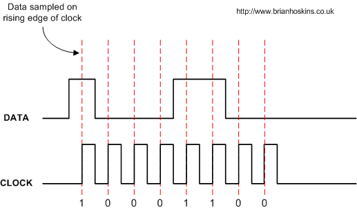
Image1

In this case, there is another wire with a clock signal on it. This clock signal tells the receiver exactly when to look at the state of the line. In this case, it's on the rising edge of the clock, the exact time at which the voltage goes from low to high. You may have many data lines and one clock line (usually parallel), or one data line and one clock line (serial). There are exceptions to this terminology when you have bidirectional data flows.

You can see here then, that as long as the clock signal is being received, bits will never be "lost". There may be noise on the data line which causes a bit to be read as a 0 instead of a 1, or vice versa, but either way it will still be one bit (if the clock line is noisy it can cause other issues).

This is known as synchronous transmission, but there also exists asynchronous transmission. This is where there is no clock line, and instead both the receiver and transmitter agree to check the line at the same time interval. There is usually some stuff done on the data line to help with initial synchronization. As you can imagine, this requires that the receiver and transmitter both agree on when exactly to sample, and are both quite accurate time-wise.

\$\endgroup\$
3
  • \$\begingroup\$ Good write up. I'd also add everything is done in packets such that timing errors have limited cumulation. Also protocols can be and are followed to detect and retry in the event of errors \$\endgroup\$
    – Trevor_G
    Commented Sep 11, 2017 at 20:50
  • \$\begingroup\$ If i may ask, sorry if this sounds really silly, how is clock implemented? If it is a computer component, wont it rely on 1 and 0 still and who will be the clock for that component? \$\endgroup\$
    – Zanko
    Commented Sep 11, 2017 at 20:52
  • 2
    \$\begingroup\$ The clock is generated by the transmitting device. I imagine that there isn't a universal method of generating a clock, but it sounds like what you're asking is "how does digital logic work?". This is a very broad question and I can't answer that in a reasonable space. If you're interested enough, you may want to read a book about it. For the moment however, it may be best to just assume that a sufficiently complex digital device (like a microcontroller) can generate any arbitrary sequence of high and low voltages, using its cpu and various supporting peripherals. \$\endgroup\$
    – BeB00
    Commented Sep 11, 2017 at 21:11
1
\$\begingroup\$

In asynchronous communication, the master and slave have to be configured to work at the same baud rate, number of bits etc. so both will know how often a data bit should be read/sent and how many bits should be expected.

The line is held high until one of the participants intending to send data will pull the line low for one bit-time (One bit time is calculated: 1/baud rate) so for 9600 baud it will be 104us. Now every 104us the data line will change and can be read by the receiver.

In synchronous communication, many data communication protocols come with an additional clock line which will be controlled by the master device. The data can then only be clocked out of the slave in sychronous with the clock line. UART uses a very basic communication method as such. When you start moving towards more advanced protocols such as I2C, SPI or in particular USB, you will find that there is much 'talk' between the master and slave which enables the master to have much greater control.

There are mechanisms to prevent data losses too with each byte which is known as parity. The master will be told how many bits were supposed to have been transferred, if it is inconsistent then it will request the slave to resend.

\$\endgroup\$

Your Answer

By clicking “Post Your Answer”, you agree to our terms of service and acknowledge you have read our privacy policy.

Not the answer you're looking for? Browse other questions tagged or ask your own question.