2
\$\begingroup\$

I'm experimenting with a couple of VL6180x distance sensors on breakouts (http://www.ebay.com/itm/172823051918, the blue ones).

Because the sensor resets its i2c adress when the power is removed, and because I want to use more than one, I need to be able to set the desired adress after boot.

My idea to solve that was to simply turn on the VIN to the sensors one after the other, and set the adress before the next one turns on. Unfortunately it seems like the sensors get power somehow even without any VIN connected. I'm guessing it's through the pullup resistors on the i2c bus.

How can I solve this? Do I have to add something to break the i2c bus connection together with VIN, or are there other better ways?

(Since the project they're intended for have limited free space, I'd prefer a solution with a low component count)

\$\endgroup\$
1
  • \$\begingroup\$ There are two solutions that come to mind. First is i2c bus switch or multiplexer. No need to disconnect when there are multiple devices with the same address. The second is a p-fet controlled by your microcontroller, connected between vcc and the pull ups. By turning it off, you can disconnect power to the pull ups and prevent the parasitic power keeping the IC on. But I'm Spitballing, this will likely need the bus switch as well. Someone else can give a proper answer. \$\endgroup\$
    – Passerby
    Commented Sep 13, 2017 at 18:35

3 Answers 3

2
\$\begingroup\$

So that's just a breakout board for this? http://www.st.com/content/ccc/resource/technical/document/datasheet/c4/11/28/86/e6/26/44/b3/DM00112632.pdf/files/DM00112632.pdf/jcr:content/translations/en.DM00112632.pdf

If so, you can hold the GPIO0 input (the 0 on the breakout board) low to put the chip into a reset state. This means you will need to dedicate an I/O line to each board, but that way you can bring them up one at a time without doing crazy things to the I2C bus itself.

\$\endgroup\$
2
  • \$\begingroup\$ +1 Agreed, I saw the same thing. It's no greater control IO requirement than powering them up individually either. \$\endgroup\$
    – Trevor_G
    Commented Sep 13, 2017 at 18:46
  • \$\begingroup\$ I kind of feel like I should have noticed that myself, since I've been reading that document a bit anyway, but apparently I missed it. Thanks for pointing it out, I've tested it with my sensors and it works great! \$\endgroup\$
    – Stefan
    Commented Sep 14, 2017 at 18:27
0
\$\begingroup\$

This is a common problem, often referred to as "back-feeding". Where an active signal can connected to a powered down board can upset its operation. It can even cause the powered down circuitry to continue operating

The usual culprit within the IC are the ESD structures used to avoid electrostatic damage - often they consist of diodes between the input signal and the supply rail.

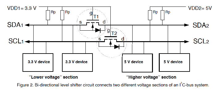
The usual way to avoid this issue is to place some form of isolator between the main bus and the circuitry on the board, often they will accomplish level shifting at the same time. There are commercial integrated solutions as well as ones using discrete devices.

I2C Level Shifter

This application note describes the operation as an isolator in section 2.3.4 on page 11 (It is not required to perform level shifting, the two power supplies can be the same voltage)
Bidirectional Level Shifter/Isolator

\$\endgroup\$
1
  • \$\begingroup\$ The breakout board do have level shifting of some sort, but I guess it's not done like this. Would there be any downsides to doing it like this, or is it just that my breakouts are cheap ebay boards that won't have extra "unnecessary" components? Thanks for the answer btw, always nice to learn something more even if it turned out I didn't need it to solve my problem! \$\endgroup\$
    – Stefan
    Commented Sep 14, 2017 at 18:37
0
\$\begingroup\$

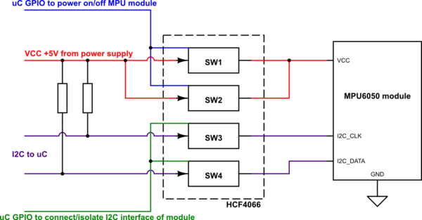
Some years ago I had a similar problem with 6-axis movement sensing modules based on Invensense MPU6050 chips - they also "talks" through I2C bus.

My solution was rather "brute force" but works excellent: for every module I've made a simple circuit based on HCF4066 quad bilateral switches. Two switches are used to switch the I2C lines, and another two connected in parallel are used to control supply voltage for MPU6050 modules.

schematic

simulate this circuit – Schematic created using CircuitLab

\$\endgroup\$

Your Answer

By clicking “Post Your Answer”, you agree to our terms of service and acknowledge you have read our privacy policy.

Not the answer you're looking for? Browse other questions tagged or ask your own question.