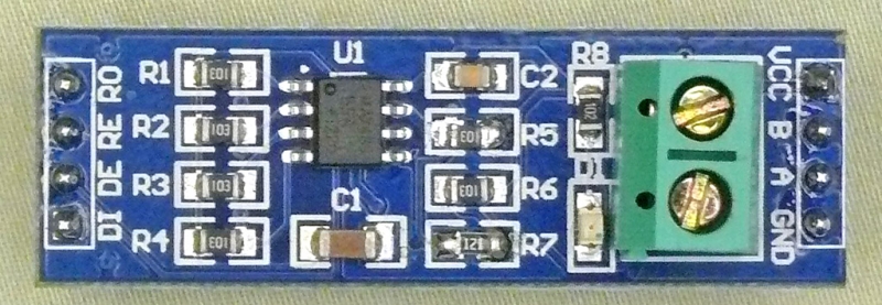
In my application, I need to transmit data between two arduinos, one as a master and the other as a slave using 485. The arduinos are connected to these modules, which have a Max485:
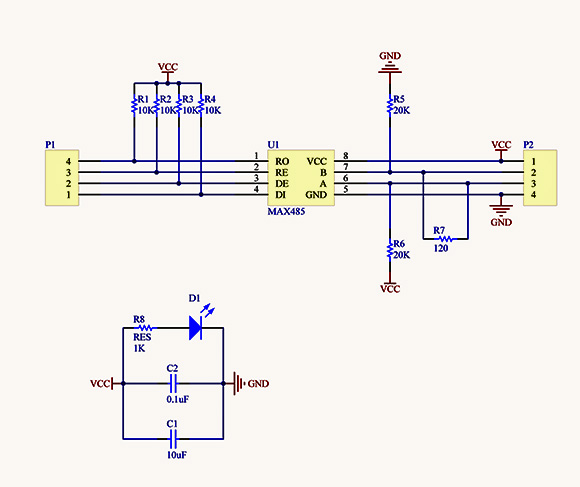
Schematic:
With these modules everything is working fine (38400 bps). Next, I want to use Max13487 so I don't have to care about the direction control lines. As I understood, Max13487 is the automatic direction control version of Max485, and their foot prints are compatible. I took these modules, desoldered the Max485, and soldered the Max13487. RE and DE (now RE and SHDW) are tied together and pulled high.
What happens next is that communication is not working. I can see data going out from the master driver, but the slave receiver is not converting it back to 5V.
The voltages on the data lines are different for the 485 and the 13487:
                   Low   High
 - MAX 485:  -A    3.3V  2.3V
 - MAX 485:  -B    1.3V  3.3V
 - MAX13487: -A    2.3V  1.3V
 - MAX13487: -B    2.3V  3.5V
What am I missing? Thanks.


REby pulling it high. \$\endgroup\$