2
\$\begingroup\$

I have a Fluke 115 multimeter available that I'm hoping has capabilities to register (even with low fidelity) any MIDI signals flowing out of a handful of devices. There's an old keyboard that I'm testing out which has the standard MIDI IN/OUT ports on the back and so far the IN port I can verify is working because sending MIDI through my laptop over a USB to MIDI cable can trigger the notes to be played on the keyboard's speakers using the MidiOx utility. However the opposite direction is not operating and I'm hoping to test that port for some basics with a multimeter.

I'm starting from scratch here and need to learn the pins and "electrical specifications" of MIDI. I don't need a full resolution oscilloscope to see the fine grained signals for each note, I'm just hoping for a basic test using something like the Hz setting on my multimeter. Looks like the Fluke unit tops out at 50 kHz so I'm hoping an aliased signal still can be captured on the multimeter that I can reliably trigger for certain keys that would indicate something is at least working. I might be out of luck there given that the wiki article states that

MIDI messages are made up of 8-bit words (commonly called bytes) that are transmitted serially at a rate of 31.25 kbit/s. This rate was chosen because it is an exact division of 1 MHz, the speed at which many early microprocessors operated.

Am I understanding things properly that pins 4 and 5 would be the ones to target? Anyone have any advice which keys to choose and if it would even matter.

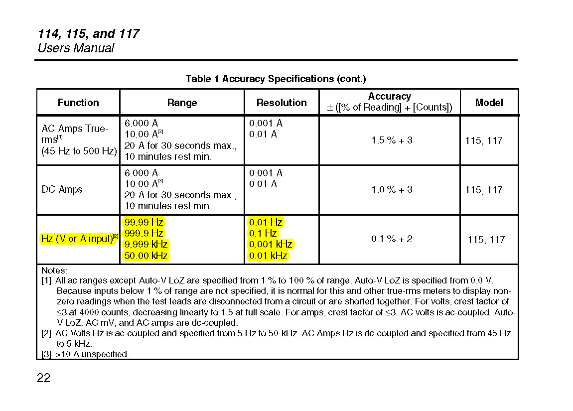
Fluke 115 Hz Function Specifications

\$\endgroup\$

2 Answers 2

1
\$\begingroup\$

MIDI is unipolar NRZ serial over twisted pair, (at 31250 baud) the serial signal drives a optocoupler in the receiver so the voltage is in the 1 to 5V range somewhere and the DC impedance ballpark 200 ohms.

set your meter to AC millivolts or DC volts and look for fluctuations or connect a high-efficiency visible LED and look for blinks

\$\endgroup\$
2
  • 1
    \$\begingroup\$ That LED was a real winner, I'll post an answer with a video showing that trick in action. Never occurred to me to bust out an LED for this purpose. \$\endgroup\$
    – jxramos
    Commented Dec 28, 2017 at 19:36
  • \$\begingroup\$ Would be nice to see a schematic and what components you used when you connected the LED. I'm trying to fix a broken MIDI out on a synth, and it would be great to be able to test it without connecting it to the computer. \$\endgroup\$ Commented Mar 29, 2021 at 15:55
3
\$\begingroup\$

MIDI uses a 5 mA current loop through pins 4 and 5. Many MIDI outputs implement this with an open-collector driver, and there is no current flowing when idle, so it is likely that you will not be able to measure any specific voltage difference between the bare pins. The mose reliable way to measure the output signal is to connect a 470 Ω resistor between these pins, and measure the voltage drop over it (or the current through it).

While MIDI itself uses a rate of 31250 baud, it is unlikely that the keyboard is able to send messages fast enough for that to be detectable (unless it has a bulk dump function). Your best bet is to use your multimeter's Hz V function, and to whack any key as fast as possible (both key press and key release will generate a message).

\$\endgroup\$

Your Answer

By clicking “Post Your Answer”, you agree to our terms of service and acknowledge you have read our privacy policy.

Not the answer you're looking for? Browse other questions tagged or ask your own question.