3
\$\begingroup\$

I'm trying to build a circuit for controlling the speed of a fan from an ESP8266 MCU. I have a PN2222 transistor with the base connected through a 1K resistor to a digital out of the MCU. The voltage at the digital out is +3.3V when it's high and I verified that I can successfully set it high and low on the MCU reading it with a DMM. So that part seems to be working.

The power supply for the fan that is being switched by the transistor reads ~18V unloaded using a DMM. However when I read the voltage of the emitter of the transistor using a DMM it reads 8V no matter whether the base is high or low.
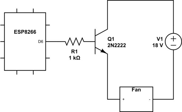
schematic

simulate this circuit – Schematic created using CircuitLab

I was expecting it to read 18V when the base of the transistor was high and 0V when it was low.

Clearly there is something I am misunderstanding here with my first foray into transistors being very new to electronics in general.

\$\endgroup\$
1
  • \$\begingroup\$ you do not say what is the reference point for the emitter voltage measurement (where you place the DMM negative probe) ... also, please add the ground to your circuit diagram \$\endgroup\$
    – jsotola
    Commented Dec 24, 2017 at 23:23

3 Answers 3

10
\$\begingroup\$

The drive should look like this:

schematic

simulate this circuit – Schematic created using CircuitLab

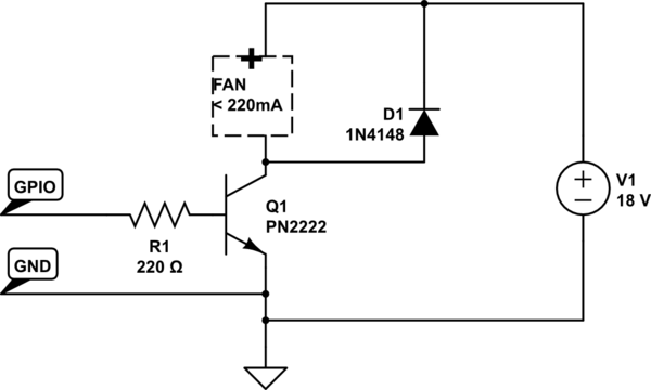
I have reduced the base resistor value to allow driving a fan of >200mA. If your fan is only 50mA or less the 1K is fine. D1 is to absorb any inductive spike from the fan motor when the transistor turns off.

Note the ground connection between the ESP and the power supply.

\$\endgroup\$
6
  • \$\begingroup\$ Huh. His question has never been edited and his transistor is most definitely a 2N2222 named Q1, with V1 as a voltage source. 2N3904 is never mentioned in the question or title. \$\endgroup\$
    – pipe
    Commented Dec 24, 2017 at 21:31
  • 1
    \$\begingroup\$ Actually it was edited- I don't know why it is not showing up! It changed between edits on mine. \$\endgroup\$ Commented Dec 24, 2017 at 21:32
  • 1
    \$\begingroup\$ Yeah, I can't see an edit history. Maybe it doesn't show as an edit if you edit it within a certain time after posting. \$\endgroup\$
    – pipe
    Commented Dec 24, 2017 at 21:33
  • 2
    \$\begingroup\$ It was edited, I saw the original version too. \$\endgroup\$
    – Wesley Lee
    Commented Dec 24, 2017 at 21:49
  • 1
    \$\begingroup\$ Stealth edits. Minor edits between 5 minutes or so are rolled into the original. So that you don't get like 8 edit histories of a few characters. \$\endgroup\$
    – Passerby
    Commented Dec 25, 2017 at 0:22
7
\$\begingroup\$

You are using the transistor in emitter follower configuartion. That provides current gain, but no voltage gain. The emitter will be one diode drop below the base, which is at about 2.6 V in this case.

If you are seeing 8 V on the emitter, the you have already blown up the transistor. It probably dissipated too much power.

Connect the emitter to ground, and put the fan between the supply and the collector. Find how much current the fan draws. That divided by the gain of the transistor will be how much base current you need to supply. Size the base resistor to allow at least that much current.

The above is assuming that transistor can handle the fan current, and that this ESP thing can deliver the base current. If the transistor isn't beefy enough, use a different transistor.

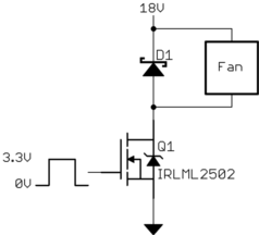
A logic-level FET like the IRLML2502 would be a good choice here. It turns on well with 3.3 V gate drive, and it can handle up to 20 V.

I would add a reverse diode across the fan to make sure that whatever transistor you choose doesn't get fried when you shut off the fan.

\$\endgroup\$
1
  • \$\begingroup\$ Whoever downvoted this, what do you think is wrong? \$\endgroup\$ Commented Dec 25, 2017 at 14:17
6
\$\begingroup\$

You were close.

The simplest arrangement is to use the transistor as a "low-side switch". When you inject some current into the base it will allow a much higher current to flow from the collector to the emitter.

schematic

simulate this circuit – Schematic created using CircuitLab

Figure 1. Rearranging the circuit for a low-side or common emitter switch.

Try this and report back.

Note: if it is a 12 V fan then you should be using a 12 V power supply - not 18 V.

\$\endgroup\$
3
  • \$\begingroup\$ Tried this and got a range of 10V to 18V with a DMM where the fan would be. Just for fun, I replaced the 18V supply with 3.3V from the ESP8266 board. Scaling the GPIO pin value (software PWM) did scale the DMM reading. But like the 18V supply when scaling the GPIO from 0 to 1023, it goes from -0.27V at 0 immediately up to 1.94V with the GPIO at 1 and 3.21V with the GPIO at 1023. Not sure if the increments between 1 and 1023 scale linearly but why the big jump from 0 to 1? The GPIO itself scales much closer to linearly with 1 reading 0.016V and 512 reading 1.65V. \$\endgroup\$
    – Brian
    Commented Dec 26, 2017 at 6:45
  • \$\begingroup\$ You're doing something wrong somewhere. I'm using PWM on an Arduino project at the moment. Post a schematic and photo of your setup. I should have added a flyback / protection diode across the fan as the others did but for some reason I am unable to edit my schematic. Try putting a 1k resistor in instead of the fan and measure the voltage across that. \$\endgroup\$
    – Transistor
    Commented Dec 26, 2017 at 6:49
  • \$\begingroup\$ Updated schematic and photo are in this question. Not sure if there was a better way to provide an updated schematic and photo. \$\endgroup\$
    – Brian
    Commented Dec 26, 2017 at 18:42

Not the answer you're looking for? Browse other questions tagged or ask your own question.