0
\$\begingroup\$

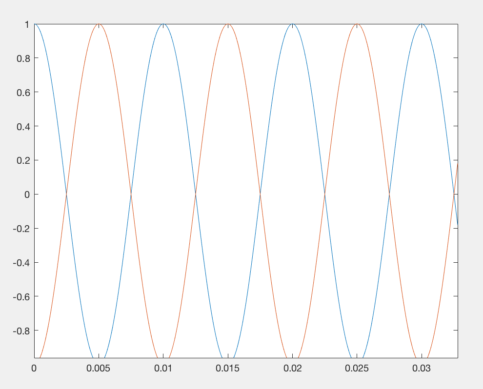
I am creating the two delayed cosine waves in picture 1 on MATLAB using the following script:

enter image description here

clear all close all %% Create sinusoidal Wave fs = 44100; t = 0:1/fs:2; T =10e-3; signal = cos(2*pi*t*1/T); %% Create shifted signal Delay = 5e-3; shifted_signal = cos(2*pi*(t-Delay)*1/T); %% Output signals soundsc([signal, shifted_signal],fs)

And then I am measuring the output signals on the oscilloscope by connecting my laptop speaker to a custom board and then to the oscilloscope.

This is what is displayed on the oscilloscope.
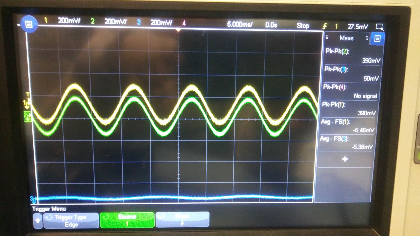
Picture 1 I don't understand why I cannot see the delay. Can someone explain to me how I can measure the delay on the oscilloscope or if there is a special set up for this? I read several articles in many websites but I haven't solved the problem. The oscilloscope I am using is a keysight infiniivision dsox3024 t

\$\endgroup\$
10
  • 1
    \$\begingroup\$ What exactly are you measuring? Your "delayed" signal is just the same as an inverted signal.. \$\endgroup\$ Commented Jan 17, 2018 at 17:55
  • \$\begingroup\$ Why do you want to measure a 5 ms delay on 100Hz signal ? \$\endgroup\$
    – D.A.S.
    Commented Jan 17, 2018 at 18:02
  • 3
    \$\begingroup\$ Maybe you have a channel on your scope set to invert. It happens like this sometimes. \$\endgroup\$
    – Andy aka
    Commented Jan 17, 2018 at 18:10
  • \$\begingroup\$ Thank you for your reply. I am doing this for learning purposes. I also tried with 1 ms delay and still, the signals are not shifted. \$\endgroup\$
    – Tesla001
    Commented Jan 17, 2018 at 19:20
  • 2
    \$\begingroup\$ This was a classic error with old style analog oscilloscopes - alternative full sweeps with alternating the trig source, too. I cannot believe this is your case, but check it. Test with single CH signal and having a RC lowpass filter generating phase lag to CH2. \$\endgroup\$
    – user136077
    Commented Jan 17, 2018 at 20:44

4 Answers 4

1
\$\begingroup\$

This is a MATLAB problem not an electronics problem. You are wanting to play two channels of audio using soundsc. However you are supplying it a row vector instead of a \$x \in \mathbf{R}^n\$ i.e. an \$n \times 1\$ vector.

If you have two vectors that are \$m \times 1\$ and concatenate them, you end up with a \$2m \times 1\$ vector, whereas if you want to play things simultaneously you want a \$m \times 2\$ matrix. What you will get is a 2 second signal followed by a click caused by a discontinuity as you switch between the original signal and the phase shifted signal, followed by another 2 seconds of sine.

Here is the fixed source code, where I have change your comma to a semicolon in the last line to create an \$m \times 2 \$ matrix.

clear all
close all
%% Create sinusoidal Wave
fs = 44100;
t = 0:1/fs:2; T =10e-3;
signal = cos(2*pi*t*1/T);
%% Create shifted signal
Delay = 5e-3;
shifted_signal = cos(2*pi*(t-Delay)*1/T);
%% Output signals
soundsc([signal; shifted_signal],fs)
\$\endgroup\$
0
\$\begingroup\$

It appears that your scope is showing both signals in real time. Which unfortunately means there is something wrong with your output.

Your could test this by outputting two synchronized unit step signals. If they appear synchronized you know that your scope and board setup is correct.

\$\endgroup\$
3
  • \$\begingroup\$ Thank you for your reply cammac. Do you have any suggestion to check what is wrong with the output? My main confusion is that I can see the delay when I plot the signals using MATLAB but not on the oscilloscope. \$\endgroup\$
    – Tesla001
    Commented Jan 17, 2018 at 19:23
  • \$\begingroup\$ Have you tried outputting two synchronized signals? If so what was the output? What does your output setup look like, you say you're using your laptop speaker, are you using the left side for one signal and the right for the other? Could it be that you're outputting the combination of the two waves? \$\endgroup\$
    – cammac
    Commented Jan 18, 2018 at 16:38
  • \$\begingroup\$ Oh I see that the combination of the two waves should be zero. \$\endgroup\$
    – cammac
    Commented Jan 18, 2018 at 16:45
0
\$\begingroup\$

I have nothing much to go on here, but I'm guessing you are measuring the same signal twice. Try playing a sine wave to only the left or right channel and verify the output.

If you are measuring the same signal, then it could be either the output being mono (left channel is played to both channels) or you could be probing the same voltage twice.

\$\endgroup\$
0
\$\begingroup\$

It does look like something is wrong with the output or probe setup - the scope won't lie to you.

Check these things:

  • Make sure you are hooked up to the right signals and don't have a probe & ground inverted
  • Make sure one of your channels isn't inverted by the scope (in the channel menus)
  • Try the pan thing as mentioned by Sven, put each signal in a different L/R channel

To measure the delay, there should be both a "delay" measurement and a "phase" measurement in the measurement menu. To get a more accurate measurement, make sure to zoom in on just one cycle and make each signal full height on screen.

\$\endgroup\$

Your Answer

By clicking “Post Your Answer”, you agree to our terms of service and acknowledge you have read our privacy policy.

Not the answer you're looking for? Browse other questions tagged or ask your own question.