0
\$\begingroup\$

I’m trying to build a Lego Technic panel with some RGB LEDs (do you know they fit perfectly in Technic’s holes?) driven by an Arduino.

Anyway, my question is: how do I connect multiple (say, 9) RGB LEDs to be driven simultaneously? I want to use RGB LEDs because, although they all have to show the same color, this color may vary. There are tons of info about how to drive them independently but I’d like to light them up all the same, like they are a single one.

The LEDs I'm going to use are Elegoo 5mm common anode (datasheet) or common cathode (datasheet).

I know I have to use an external power supply, probably transistors activated by Arduino to power the LEDs and resistors but I have no idea about the whole circuit, what goes where. I don't have a power source yet but best thing would be to use USB from PC, if it would suffice.

LEDs need to be driven from an Arduino UNO which decides what color and luminosity to display; this is going to be some kind of semaphore on my desk.

I know the question is a bit broad but worth a shot. Any help would be really appreciated.

\$\endgroup\$
9
  • \$\begingroup\$ WHat do you have for a power supply, what is the part # of the leds, how are you controlling them..... \$\endgroup\$
    – Trevor_G
    Commented Feb 8, 2018 at 17:44
  • \$\begingroup\$ "I’d like to light them up all the same, like they are a single one." Just checking: you want R+G+B to turn on simulutaneously? Why not use 2-pin white LEDs which could be series connected? You can't easily series connect 4-pin RGBs. As Trevor says, link to datasheet for the LEDs, please. Put all the info in your question rather than sprinkled through the comments. \$\endgroup\$
    – Transistor
    Commented Feb 8, 2018 at 18:05
  • \$\begingroup\$ Note that “sorry I’m noob” is not obligatory. \$\endgroup\$
    – Samuel
    Commented Feb 8, 2018 at 18:10
  • \$\begingroup\$ It is if you are @Samuel \$\endgroup\$
    – ccalboni
    Commented Feb 8, 2018 at 18:22
  • \$\begingroup\$ I’ll gather the required info @Transistor anyway I’d like to use RGB because I want to drive them all together but with varying colors \$\endgroup\$
    – ccalboni
    Commented Feb 8, 2018 at 18:23

3 Answers 3

2
\$\begingroup\$

schematic

simulate this circuit – Schematic created using CircuitLab

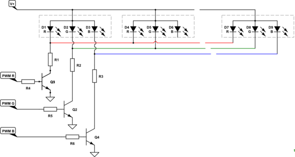
Figure 1. The non-ideal but probably best solution given space constraints.

  • LEDs' current consumption rises exponentially with voltage. i.e., A small increase in voltage can result in a large current and this can damage the LED.
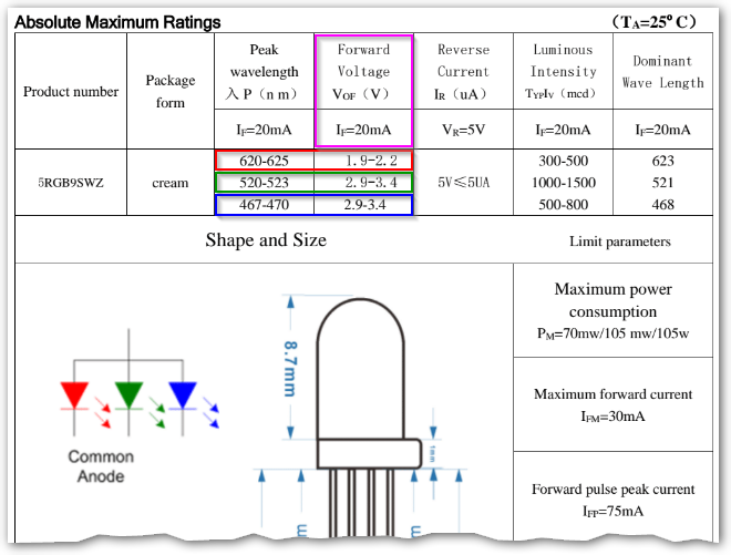
  • Looking at Figure 2 we can see that at 20 mA (2/3 of the rated maximum) the voltage varies quite a bit. For this reason it is usually recommended that LEDs are not connected directly in parallel because the one with the lowest forward voltage will pass a disproportionally large current with possible failure as a result.
  • In your scheme you don't have room for individual current limiting resistors and, due to the common anode, can't series connect the LEDs so we'll have to deal with parallel LEDs in a safe manner.

enter image description here

Figure 2. Extract from the datasheet. Notice the wide variation in forward voltage within each LED colour.

Using the scheme of Figure 1 we can parallel the nine LEDs. We now need to calculate the resistor values. We'll limit the current to an average of 10 mA per LED giving 90 mA max per channel when it's switching transistor is on. We'll also use the mid-range forward voltage for each colour LED and we'll ignore the small voltage drop between the collector and emitter of the transistors when on. Finally, I'll assume a 5 V supply.

Colour     V LED      I         Voltage across R     R = V / I
R          2.05 V     90 mA     5 - 2.05 = 2.95 V    _______ Ω
G          3.15 V     90 mA     5 - 3.15 = 1.85 V    _______ Ω
B          3.15 V     90 mA              = 1.85 V    _______ Ω

I'll leave the calculation to the reader.

\$\endgroup\$
9
  • \$\begingroup\$ Dang, beat me. Yours is more complete. \$\endgroup\$ Commented Feb 8, 2018 at 21:11
  • \$\begingroup\$ It's tough in here! Undelete yours even just to reinforce or complement mine. The addressable LEDs are worth looking at. They don't need resistors if I remember correctly. \$\endgroup\$
    – Transistor
    Commented Feb 8, 2018 at 21:16
  • \$\begingroup\$ "you don't have room for individual current limiting resistors": Not if he uses SMD 0604 resistors. \$\endgroup\$
    – Fredled
    Commented Feb 8, 2018 at 21:17
  • \$\begingroup\$ Judging by the nature of the question I didn't even consider surface mount. Maybe ... but I think wiring and insulation will be more of a problem than the SMDs themselves. \$\endgroup\$
    – Transistor
    Commented Feb 8, 2018 at 21:18
  • \$\begingroup\$ Well... will learn manual soldering of tiny SMD components at the same time. ;) \$\endgroup\$
    – Fredled
    Commented Feb 8, 2018 at 21:20
2
\$\begingroup\$

Like this. Pick the resistors to get the appropriate current for each LED, making the resistors the same for each color. There thus may be 3 sets of resistors. See Transistor's answer for considerably more detail.

You can drive the transistors with PWM if you like.

schematic

simulate this circuit – Schematic created using CircuitLab


Or use the WSxxx individually adressable LEDs and simply send the same brightness information to each, which is easier and more flexible. Using the Arduino libraries it is very fast to do that, and the PWM brightness control is done inside the driver chip.

There are even 4-LED SMT parts that contain a serially accessed driver chip, RGB and a white LED.

\$\endgroup\$
1
\$\begingroup\$

Ok: On each LED you have one Anode (+) and three cathodes (-), one for each color. (see shematic on the datasheet "common anode") It means puting them in serie is impossible so you must put them in parallel. To do that:

  1. connect a resistor to each cathode (resistor value depends on mA and voltage). --- Resistor calculator --- another resistor calculator (read)
  2. Connect every pin of the same color (with their resistor) to the same line.
  3. Connect each line to an N-Chanel Mosfet or a NPN transistor. In this simple configuration, you will be able only to turn on or off color channels without variation. But if you achieve that, it's already a very good start for the next steps. Like this but, obviously, with the control part being different. Also in this diagram, the resistor is on the anodem while you have to put it on the cathode. Each set of 3 led is like one color of a 3 color leds. Here related discussion and here (look at diagrams)
\$\endgroup\$
2
  • \$\begingroup\$ It's quite clear, I just lost you after the "good start"; but let me ask, if the color I want to use are red, green and yellow (like a traffic light), maybe I don't need an analog output, I can use digital red=1, green=1, blue=0 to show the yellow. In this case it should be easier. \$\endgroup\$
    – ccalboni
    Commented Feb 8, 2018 at 20:59
  • \$\begingroup\$ Yes, that's what I meant: It will be easier to do as you said: red = 1, green = 1, blue = 0. These types of combinations. Having variable colors would be more difficult, but not impossible, later, if you want to. \$\endgroup\$
    – Fredled
    Commented Feb 8, 2018 at 21:12

Your Answer

By clicking “Post Your Answer”, you agree to our terms of service and acknowledge you have read our privacy policy.

Not the answer you're looking for? Browse other questions tagged or ask your own question.