What are effects of interwinding capacitance in smps power transformer? What is the influence? For example, i have 83khz smps transformer with windings made of litz wire. The capacitance between windings is 250pF (i measured it by short-circuiting both windings and using u1732c agilent RLC meter). Is it good or bad? Is electrostatic shield between primary and secondary helpful to reduce value of inter-winding capacitance?
2 Answers
What are effects of interwinding capacitance in smps power transformer?
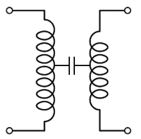
The easiest way to think about the main noticable effect is to lump that distributed capacitance into one component: -
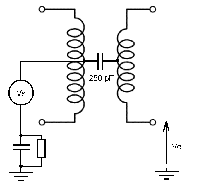
Then consider what mid-point voltage you have on the primary and what the possible impedance to earth is: -
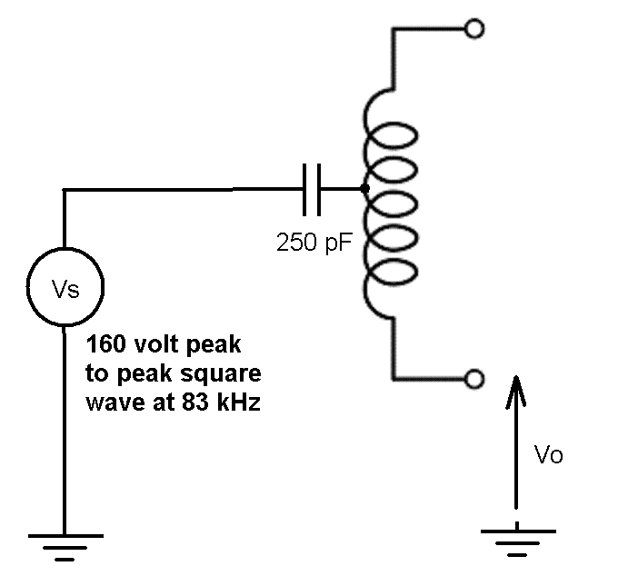
At the switching frequency, the peak-to-peak voltage on the primary winding might be 230V x 1.414 = 325 volts. This is the rectified DC bus voltage converted into a square wave at the switching frequency. The "effective" mid point voltage is about 160 Vp-p (an 83 kHz square wave approximately).
For an SMPS, the incoming lines are either coupled via capacitors to earth or live/neutral is regarded as "earth". We can now paint a scenario where we have 160 Vp-p at 83 kHz coupling via 250 pF to the output secondary winding. The scenario is likely to have very little impedance where I've shown a resistor and capacitor in parallel because of the switching frequency: -
This of course creates a lot of common-mode noise on the output of the SMPS and what manufacturer's do is add capacitors from the output to ground (if ground is available) to form a high frequency potential divider with the 250 pF interwinding capacitance. Thus, the high frequency 160 Vp-p seen on the secondary is reduced considerably with respect to earth and the device passes EMC testing.
When the SMPS uses a two-pronged earthless AC connection, a capacitor is usually added from secondary back to the "steady side" of the primary in order to try and flush the output noise down to earth via AC wiring. This produces a knock on effect of now seeing AC mains frequencies on both output wires of the SMPS - the subject of many questions on this site.
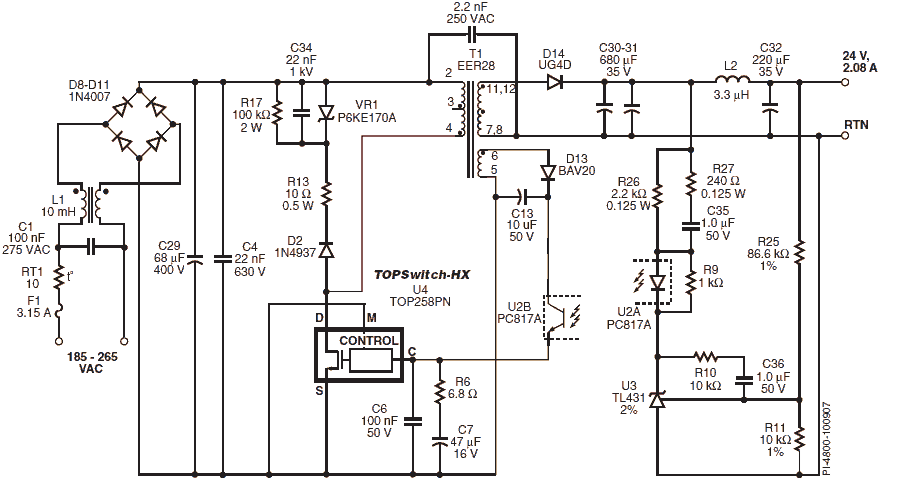
Typical example used by Power Integrations: -
Note the 2.2 nF 250V AC capacitor just above the transformer - this is that capacitor used to reduce output noise but also leaches 50/60 Hz to the output.
Is it good or bad?
It is what it is. Bigger transformers will have more capacitance and this cannot be avoided sometimes.
Is electrostatic shield between primary and secondary helpful to reduce value of inter-winding capacitance?
Only if you can connect it to earth - if you can't it probably makes the primary-secondary cross-coupling even greater.
-
\$\begingroup\$ @silkyre6xtenz if you are happy with an answer then please consider formally accepting it else raise a comment to get clarification. \$\endgroup\$– Andy akaCommented Mar 11, 2018 at 11:34
Please note that in a high frequency transformer the effective inter winding capacitance has several effect, not all of them being linear!
Ideal model would need to distribute the winding capacitance across the whole contact surface, but actually working with two capacitors connected at each end of the winding works for most situations.
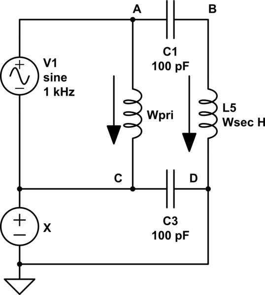
simulate this circuit – Schematic created using CircuitLab
In this case, the two windings are in parallel so the voltage A->B and C->D remains identical at all times (it is equal to the voltage x).
Now take the same transformer, but place the secondary winding in the other direction (I mean, mechanically wound in the opposite direction).
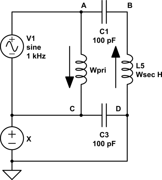
Now on this schematic, the voltage C->D remains equal to x, but the voltage A->B is now equal to x minus twice V1(t)
In this case, the inter-winding capacitance is no longer hidden from V1 and this is having quite some effects.
Let's see : if V1 was 1V with respect to the x source, then at the same moment B is -1V with respect to ... GND
How much voltage (ignoring DC voltage x) is there across capacitor C1? 2V, 1V due to A being above C, one other due to B being below D.
Because there is voltage, there is current; but because x is constant, this current cannot flow through capacitor C3 and fully flow through the source x!
So now if you were to measure capacitance across the source x (which would be the primary secondary capacitance) you would get a result depending on the frequency at which you measure the capacitance. Due to the internal way LCR meters measure (often RMS current/voltage measurement with low pass filtering of the measured impedance), you would get a capacitance increasing at the LCR meter get close to 1kHz, aliasing (getting very high and very low results) at 1kHz and then decreasing again.
So what is now the capacitance between primary and secondary? At the very least no longer a single value; and depending on the aliasing happening, not even a linear capacitor any longer.
To limit this effect, engineers place a capacitor across the two cold points of a transformer (in this case, CD) to limit the current flowing through x (you need in this case to consider x is not a true short circuit, at least for high frequencies).
Back to your question
The inter-winding capacitance of a transformer is by itself not an issue. Only thing is, once the transformer is not 100% symmetric (like in my example, or also 10 turn pri, 2 turn sec) high frequency currents start to flow through the "source" x, generating common mode noise. Those noises are a big problem and cost a lot of money to filter out! Because they flow through the whole cables back earth (the source x), the very long travel distance mean they can radiate very effectively.
For example, a 1MHz V1 source would start making any AC cable above 3m into an antenna. THIS is a big problem.

