This is about for low level signals interference/noise being observed with single ended data acquisition inputs but not with diff inputs. Basically there are three data acquisition boards, where one of them is a single-ended USB board, the other one is a single-ended earth grounded PCI board(can be set for diff ended as well) and the third one is diff-ended USB board. All are monitored by a desktop PC. Sampling rate is set to 1kHz for all. And all boards have the same resolution.
When I couple a source to inputs of these boards normally if there is no interference and noise I don't get issues for DC signals like 5V DC.
But sometimes I observe noise issues with single ended PCI board so I wanted to investigate about these empirically.But for this I needed a source with interference. Luckily I guess I found one. A function generator signal is read differently by the boards depending on they are single or diff ended.
I use this function generator as source for input signals to the data-acquisition boards. I set it to 10mV pk-pk 3Hz sinusoidal with no offset. So a good measurement should measure a similar signal which should resemble a 10mV pk-pk 3Hz sinusoidal. I use both STP and BNC coaxial cables. In this example I will use BNC coaxial cables.
First I use the function generator with 3-prong power cord. The function generator's output signal ground is connected to the mains earth through the power cord just like in a scope.
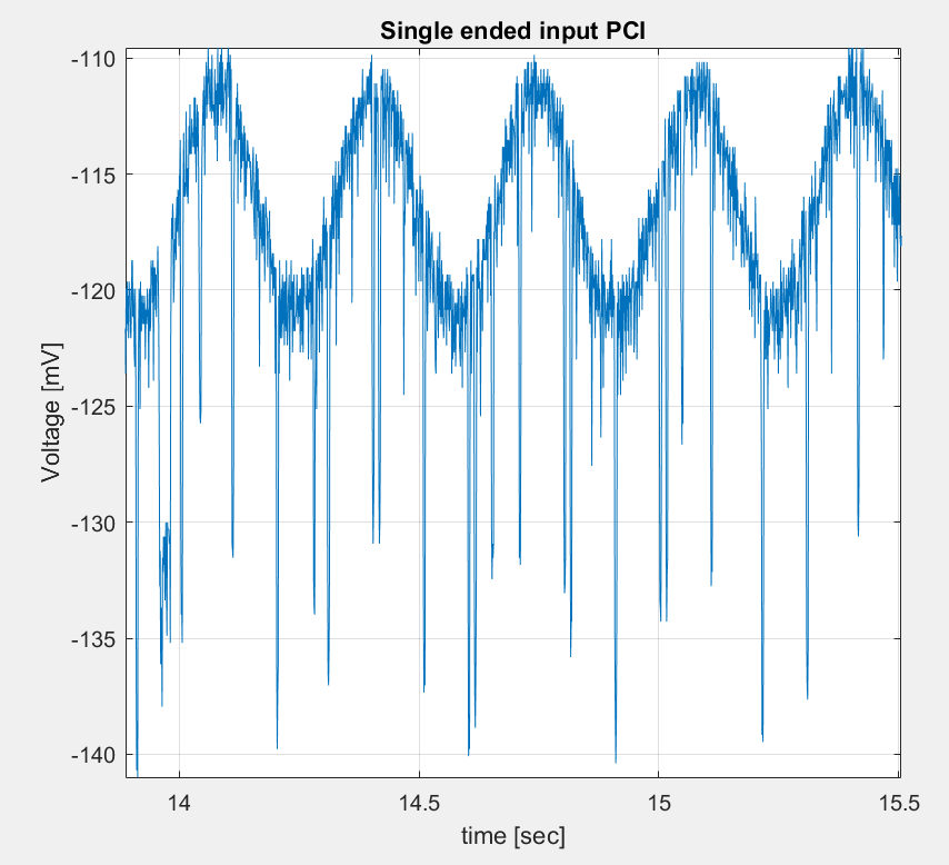
So first I use it with 3-prong power cord. Then I measure with the PCI single-ended earth grounded board and here is what it measures:
Above you can see the offset error and distortion in the signal.
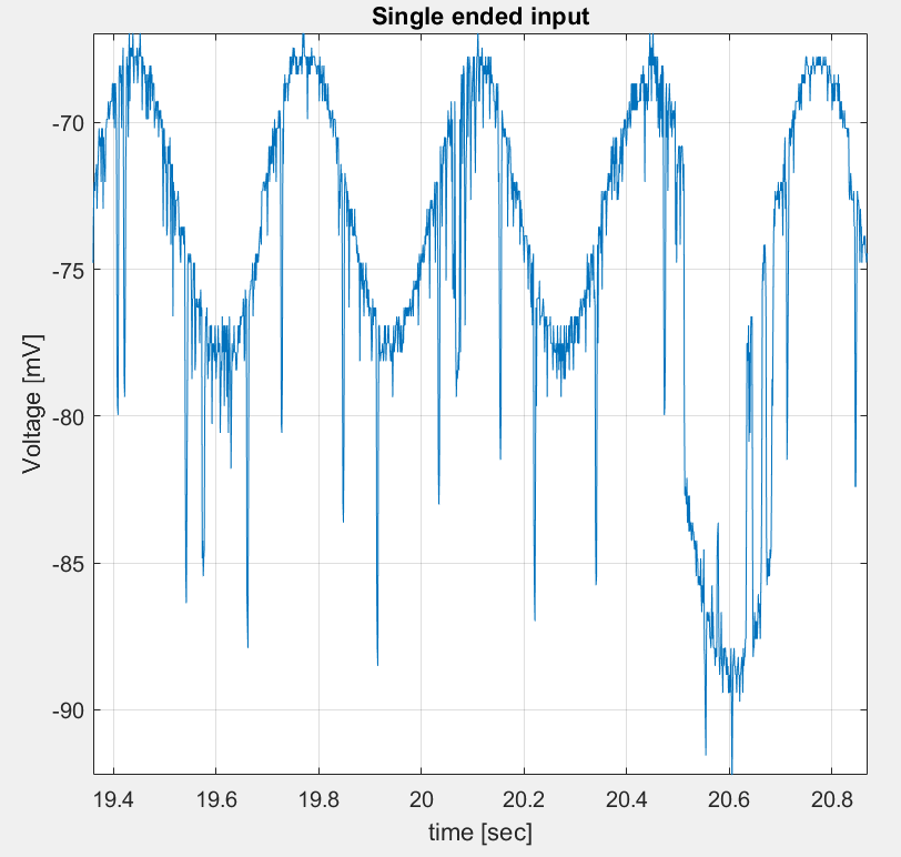
And now I set up the same measurement with the single-ended USB board. Notice its ground is not earthed. And here I get the same problem:
There is offset error with significant distortion.
I noticed this distortion gets bigger with the cable length.
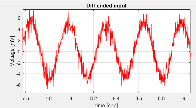
And finally here is the result from the diff-ended board's measurement:
Above there is almost no offset error and the noise does not distort the signal much. Looks like random noise. I also get similar measurement if I use the PCI board as diff ended input config.
And after all these I concluded diff-ended inputs are more immune to noise.
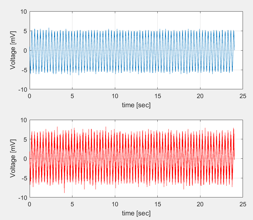
But then I used two-prong power cord for the function generator and the single-ended boards started to measure very accurate even a bit better than the diff-ended.
My questions are:
1-) I use cables around 15 meters up tp 50 meters. And seems to me like if there is no interference single ended is great. But when there is noise the dif-ended is better. In my case what could be the reason that using three-prong power cord for the function generator causes tis interference?
2-) How does this noise appears as offset and distortion in single-ended and does not appear at the diff.ended daq board?
3-) I want to show it to people to convince to use diff.ended board for better measurements. I was looking for long time a noisy interference scenario to test two systems single and diff ended but I failed to create interference. Can my setup be used to demonstrate the difference of these two systems(single vs diff ended)?
EDIT:
As I mentioned if I use 2-prong power cord(i.e no interference), I obtain the single-ended(blue) data even better than the diff-ended(red) case as below:


