1
\$\begingroup\$

Capacitive proximity sensors rely on a change of capacitance to alter the resonant frequency of the oscillator circuit. However I'm unsure as to what type is generally used in industrial type sensors.

The types of oscillator I'm most familiar with are LC type such as Colpitts and RC type such as Wein Bridge.

Which of these (if at all) are used more commonly in industrial type capacitive proximity sensors?

\$\endgroup\$
5
  • \$\begingroup\$ RC oscillators do vary their frequency ... look at the units of 1/RC. \$\endgroup\$
    – user16324
    Commented Mar 22, 2018 at 15:54
  • \$\begingroup\$ @BrianDrummond this is where my confusion lies, im well aware that both have resonant frequency associated with either or. The proximity sensors i've looked at generally rely on an amplitude change, this is obviously not directly tied to the oscillator but an intermeidiary circuit. My guess was that RC would be used for amplitude where as LC would be frequency based. Ill remove to avoid confusion. \$\endgroup\$
    – Pop24
    Commented Mar 22, 2018 at 16:04
  • 1
    \$\begingroup\$ RC C tuned f can easily be done with stable R values in a Relaxation Oscillator and stable voltage regulator Even the CMOS Schmitt trigger will work well. \$\endgroup\$
    – D.A.S.
    Commented Mar 22, 2018 at 17:18
  • \$\begingroup\$ It depends on the size and variation of C what to use \$\endgroup\$
    – D.A.S.
    Commented Mar 22, 2018 at 18:51
  • 1
    \$\begingroup\$ Phase shift is also an excellent method, especially when there is a variable loss component (affects RC frequency and amplitude) or high loss (stops oscillation). It can be easily arranged to respond to the L or C component of the pickup, while ignoring the R. I have been thinking that the little configurable logic cells in recent micros might be quite useful for this. \$\endgroup\$
    – Henry Crun
    Commented Mar 22, 2018 at 23:24

3 Answers 3

1
\$\begingroup\$

As there are plenty of RC suggestions I thought I would summarise 2 key difference between using LC and RC oscillators.

Voltage and Temperature

  • LC oscillators are primarily dependent of L and C and not the active components or supply voltage.
  • RC oscillators are dependent on voltage thresholds to set the frequency. These are temperature dependent, and often supply voltage dependent. This was a big issue 30 years ago, not so much now if you use stable voltage regulators and precision op-amps.

LC oscillators have low phase noise compared to RC oscillators, and much greater supply noise immunity. This means that an LC arrangement can resolve much smaller changes in L or C (per unit measurement time)

When using an external C, the LC has two further advantages:

  • the tank circuit rejects out of band noise picked up by the open C sensing plate, since it is resonant
  • the frequency is not sensitive to loss R in the sensing C. If there is significant resistive loss this is part of the frequency of many RC oscillators

The LC oscillator was a simple transistor circuit (ideal for gooping in an M12 tube) at a time when a decent RC oscillator was complex with DIP IC's

\$\endgroup\$
1
\$\begingroup\$

There are plenty of capacitance probes but I feel compelled to explain the type that I have been involved with.

The type of oscillator was based around a common-collector colpitts circuit and used an operating frequency of around 10 MHz. Using this frequency you get a decent signal when there is a high speed situation to be detected such as on the blades of a turbine passing at full speed. The 3 dB bandwidth was up to 70 kHz from memory.

The down side is that at 10 MHz, transmission line effects came into play so this was utilized to good effect; a changing capacitance at the end of the probe became a changing inductance at the oscillator terminals and frequency was modulated as metal passed-by the probe end.

More often than not an LC oscillator is used (in my types of application) but I can't rule out that an RC oscillator design is used in some other applications.

\$\endgroup\$
6
  • \$\begingroup\$ Funnily enough these were predominantly what i was looking at, owing to the high temperature capabalities but was unaware of the oscillator type, thanks for the insight. \$\endgroup\$
    – Pop24
    Commented Mar 22, 2018 at 16:30
  • \$\begingroup\$ The L needs a PTC cap to offset thermal NTC of L but limited options for PTC values. \$\endgroup\$
    – D.A.S.
    Commented Mar 22, 2018 at 17:32
  • \$\begingroup\$ @TonyStewart.EEsince'75 the inductor is the reflected capacitance at the probe tip transformed to inductance by t-line effects. \$\endgroup\$
    – Andy aka
    Commented Mar 22, 2018 at 17:51
  • \$\begingroup\$ Right I meant to direct that to pop 24 in case he decides to use real inductors \$\endgroup\$
    – D.A.S.
    Commented Mar 22, 2018 at 18:50
  • \$\begingroup\$ The 1/4wave transmission line is about 5m in coax @ 10MHz. @AndyAka Can you draw a circuit of how the colpitts is connected to the probe coax? i.e. what does the tank circuit look like \$\endgroup\$
    – Henry Crun
    Commented Mar 26, 2018 at 19:49
1
\$\begingroup\$

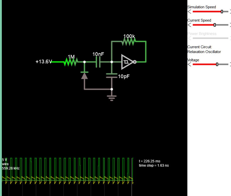
There are many ways to do this.

Here I just demonstrate using a diode to change capacitance using an RC Relaxation Oscillator.

enter image description here

\$\endgroup\$

Your Answer

By clicking “Post Your Answer”, you agree to our terms of service and acknowledge you have read our privacy policy.

Not the answer you're looking for? Browse other questions tagged or ask your own question.