9
\$\begingroup\$

I built a rather cheap(~€100) 3 axis CNC router for my workshop for cutting wood and aluminium in all sorts of fancy ways. It works great for most stuff but for things that require high precision, its always a little off.

For example, if I make it do 2 identical cuts, one right after another, the difference in any axis can be up to 1mm. Not too bad for wood, considering the total work area is 800x800x400mm and the size of things I make but kind of a problem for aluminium pieces that have to fit together.

It can be worse if significant amount of time/work is between the 2 cuts. I've had identical cuts made a few days apart for replacement parts differ by up to ~2.5mm on large pieces.

Now I figured I could get better rails, better bearings, engines, whatever to try and make it more consistent but I think the biggest gains could be had by having the ability to calibrate and check it in software.

TLDR: So what do people use for measuring distances of up to 1000mm with lets say 0.1mm precision?

I looked around chinese estores but all I found was laser sensors for large distances, like 100m with precision +- 0.2m and ultrasonic proximity sensors for shorter distances but pretty terrible precision.

They were pretty cheap though (<€10) which gives me hope. I also have the advantage of having complete physical control over both the points that I want to measure the distance between instead of just one.

\$\endgroup\$
8
  • 1
    \$\begingroup\$ if you are using stepper motors, then you can count steps .... each step represents a particular distance \$\endgroup\$
    – jsotola
    Commented Mar 22, 2018 at 19:11
  • \$\begingroup\$ It seems your errors are non repeatable so detection is easy, correction is not if you have compliance and stiction anywhere in your gantry. Stepper torque varies significantly with microstepping which under load causes position error. Understand first what causes the error. What is your relative position resolution for a full step and microstep? On my 1x1m gantry I have 0.4mm full step resolution and can choose any microstep resolution but this compromises torque. So what do U have and what do you need? \$\endgroup\$
    – D.A.S.
    Commented Mar 22, 2018 at 19:15
  • 1
    \$\begingroup\$ @jsotola Yea I'm using steppers but I'm already counting the steps, the amount of steps for moving the lead nut from one end to the other is always the same but in between, the position I get per x steps is not the same. \$\endgroup\$
    – user81993
    Commented Mar 22, 2018 at 19:23
  • \$\begingroup\$ @TonyStewart.EEsince'75 I haven't even gotten into microstepping yet (writing the software myself). The movement for 1 full step should be 0.31mm. I would be totally satisfied with 0.31mm precision if it would actually achieve that. \$\endgroup\$
    – user81993
    Commented Mar 22, 2018 at 19:26
  • 1
    \$\begingroup\$ Search for machine tool DROs (Digital Readouts). There are cheap Chinese ones using the same tech as digital calipers that will do the job. \$\endgroup\$
    – user16324
    Commented Mar 22, 2018 at 21:26

8 Answers 8

8
\$\begingroup\$

I think you should get to the bottom of what is causing your errors. Either you are missing steps or your mechanical setup is too flexible or has backlash in the nuts/bearings. Your homing switches may also have poor repeatability if you are not using an edge finder to locate the tool precisely. Or perhaps it's a combination.

Things like backlash and flexibility are very difficult to compensate for with software. For example, depending on the direction of cut you may start off with the tool in the right position but as soon as it bites in kerchunk and you've dug into the work as the cutter pulls itself in. Or you may be doing climb milling and the cutter runs well outside of the desired path if the gantry and slides are too flexible.

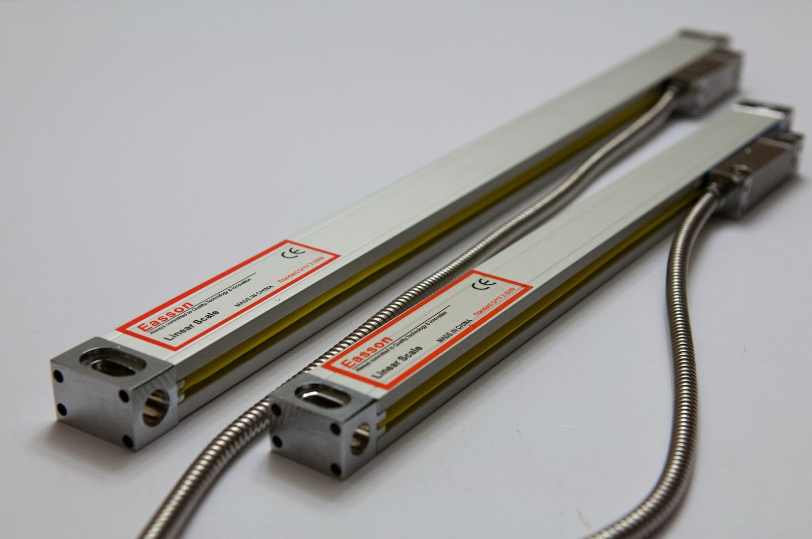
Anyway, glass scales are a sort of mid-priced way to measure a few microns down to 1um resolution. Accuracy over the full scale might be 10-15um over 1m for a cheap one. They typically have a quadrature 5V digital output (incremental), some may have quadrature sinusoidal signals. But each axis will probably cost about as much as you've put into this so far, and there is no guarantee you will be able to do much better in part accuracy. Photo from this page

enter image description here

If you win the lottery you can consider Renishaw and Heidenhain encoders, which can reach resolutions orders of magnitude less than a wavelength of light and do it with absolute measurement.

\$\endgroup\$
4
  • \$\begingroup\$ Renishaw and Heidenhain encoders are not as precise as you claim them to be. They have repeatability around the micron range per meter: renishaw.com/en/tonic-encoder-series--37824. The read head may have high resolution, but this does not coincide with the physical position of the system. \$\endgroup\$
    – user110971
    Commented Mar 23, 2018 at 11:38
  • \$\begingroup\$ @user110971 I said nothing about accuracy, only resolution. The rotary ones we are using have linear resolution in the nm and installed accuracy claimed +/-1 arc second, which is sub-ppm accuracy, similar to what you say. Resolution is also important for control. \$\endgroup\$ Commented Mar 23, 2018 at 17:00
  • \$\begingroup\$ I see what you mean. But you can get any resolution you want by implementing the interpolation yourself. You can set the encoder interpolation to one and then the gray counter outputs the reference marks. \$\endgroup\$
    – user110971
    Commented Mar 23, 2018 at 17:10
  • \$\begingroup\$ @user110971 The ones I am using at the moment have a 27-bit (IIRC) digital output, all the calculation is done internally. \$\endgroup\$ Commented Mar 23, 2018 at 17:47
5
\$\begingroup\$

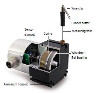
Have a look at draw-wire sensors or "yo-yo encoder".

enter image description here

Figure 1. A draw-wire sensor. Source: Environmental Engineering.

I couldn't find an image of one with a built-in display but someone must be making them.

\$\endgroup\$
4
  • \$\begingroup\$ This looks quite cool! Do these somehow enforce a single layer of winding? The measurement is rotary, so if the wire wraps over itself the radius changes. Since the OP is looking for 1mm or better, the wire (in the link) is 0.8mm and there's a \$2\pi\$ in there somewhere... \$\endgroup\$
    – uhoh
    Commented Mar 23, 2018 at 4:31
  • 1
    \$\begingroup\$ I've wondered the same thing. I've used them but never opened one up. One possibility is to advance the wire drum on a 0.8 mm pitch lead screw to align the empty portion of the drum with the entry hole. They work! \$\endgroup\$
    – Transistor
    Commented Mar 23, 2018 at 7:23
  • \$\begingroup\$ This is cool, but I seriously doubt it would be capable of CNC level accuracy. \$\endgroup\$
    – Drew
    Commented Mar 26, 2018 at 5:35
  • 1
    \$\begingroup\$ What is CNC level accuracy? Siko, for example, quote ±0.15 mm for ≤30 m extension at ≤800 mm/s for their encoders. \$\endgroup\$
    – Transistor
    Commented Mar 26, 2018 at 6:09
5
\$\begingroup\$

I hate to be the bearer of bad news, but you have stumbled into one of the major problems in machining: repeatability. It is not easy to fix in a cost effective manner.

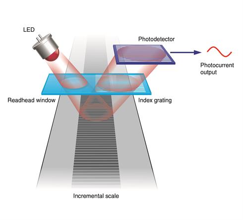
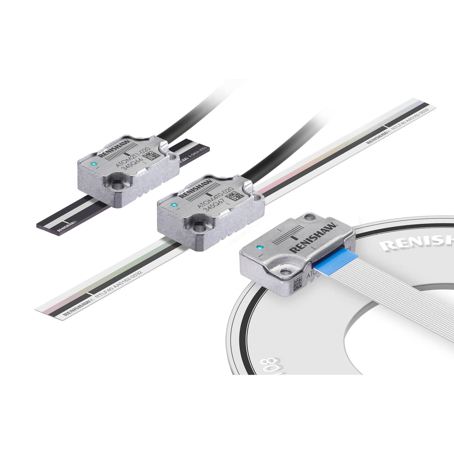
What is typically used is optical encoders with diffraction gratings. encoder A linear scale is attached to one part of the machine and the encoder read head is attached to the other. A laser is typically used to make microscopic incisions, called marks, into the scale. As the read head moves between two scale marks it outputs a sine wave due to diffraction. The markings are typically around \$20\mathrm{\mu m}\$ apart. This is what they look like: encoders

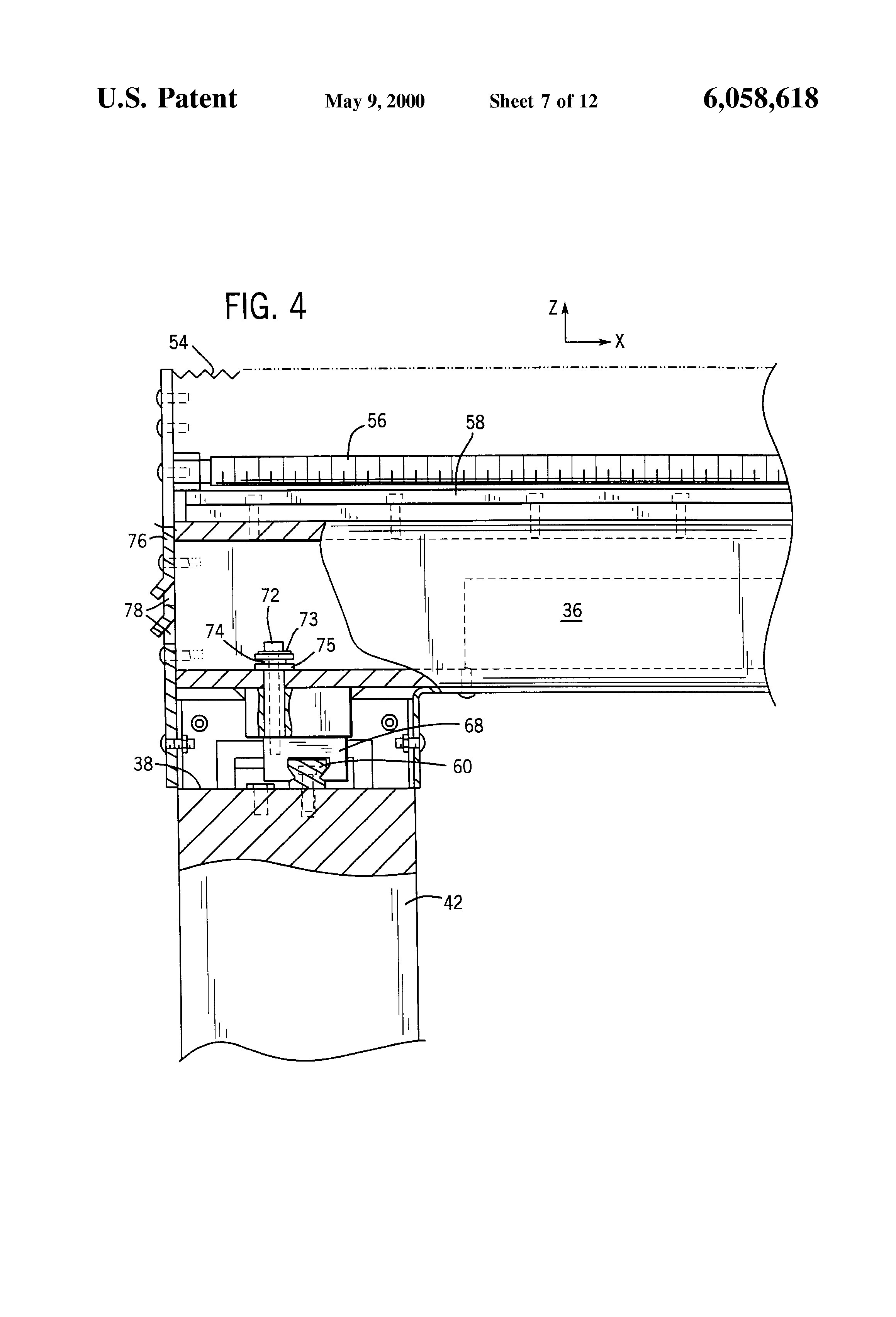
Furthermore, you will have thermal expansion problems. A one meter aluminum beam will expand by \$23\mathrm{\mu m}\$ per degree Kelvin / Celsius. If the parts of your machine are securely fixed together, the beams will buckle, due to different parts of the machine having different lengths and the expansion being proportional to the length. This is why you use holes that are larger than your bolts with rubber washer so they can move, as shown in US patent 6,058,618: cmm

I’ve tried to be brief and pointed only the major issues. I have avoided things like bearings, calibration, tool wear etc. Hopefully this can point you in the right direction. All in all, to solve these problems you need to spend a lot of money. The encoders alone are more expensive than your CNC machine.

\$\endgroup\$
2
  • 1
    \$\begingroup\$ Don't tell me the idea of having bolt holes larger than the bolts is patented... \$\endgroup\$ Commented Mar 23, 2018 at 3:19
  • \$\begingroup\$ @immibis patent expired. It used to be in the type of CMM they had patented. Now everyone can use it. \$\endgroup\$
    – user110971
    Commented Mar 23, 2018 at 9:21
3
\$\begingroup\$

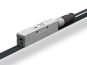
How about Magnetic Linear Encoder Tape? You can often find it and the associated sensors on eBay. The tape is encoded with opposite pole magnets at a fixed spacing between poles. A separate magnetic head senses the pole positions and interpolates between them for higher precision. A standard pole spacing on the tape is 1mm, and interpolations of 10, 25, and 50 steps between the poles are available. The control electronics measure the movement of the sensor relative to the magnetic tape.

enter image description here

\$\endgroup\$
2
\$\begingroup\$

If you look for cheap digital readouts (DRO) you'll find ones that have data ports. They will not only provide the data over the port, but on an LCD with options for zeroing the axis:

https://www.amazon.com/gp/product/B01G5SUZEG/

They can be used as sensors once attached to your machine, and if you do read them you'll get closed loop feedback for your control system which should resolve your repeatability errors with a resolution much greater than your target 0.1mm.

\$\endgroup\$
0
1
\$\begingroup\$

Distances this large are generally measured (for calibration) using an indicator against a reference bar. You can get dial indicators accurate to 0.01mm at a reasonable price, and you should be able to get someone to machine a steel or SS bar or rod to 1000mm pretty inexpensively (or you can pay 2K+ for a "real" metrology reference bar). Note that the bar will only be 1000mm at a specific temperature.

(attach the dial indicator to the spindle)

Google "metrology" and you will find a wealth of material on techniques and products.

You could also add inductive sensors to the motion rails at a specific distance apart and verify the distance as part of the calibration process each time you mill something.

\$\endgroup\$
1
\$\begingroup\$

If you want to R&D a position-reader you can build yourself, you might try a bar with alternating magnetic field regions scanned by a couple of Hall effect sensors for quadrature output. (I have not tried this!)

Rubber refrigerator magnets often have alternating magnetic field regions. The precision and region spacing would depend on manufacturing quirks for each product. But if you just want repeatability it should work OK as long as you're cutting at the same place on the bed each time. And if you calibrate it you can compensate for irregularities in software.

I thought of using magnetic audio tape - feed a constant (20-60 Hz) sine wave into a good-quality cassette recorder and you'd get a pretty regular pattern. But the field strength would not be sufficient to register on a Hall sensor without very sensitive electronics.

You might also try 3D printing a ladder grid and using optical sensors. Several years ago at Maker Faire I saw a robot with 3D printed encoder wheels on the joints. They used machine learning to learn the quirks of each spoke of the wheels, and claimed amazingly high precision plus absolute registration!

\$\endgroup\$
0
\$\begingroup\$

A year or so back I completed a project where we measured distance to about 1.5uM using a laser trisensor. This is a laser sensor with a diffraction grating, where the beam is directed at a flat surface. Distance is output as a 16 bit int, you convert to mm using manufacturers formula. The sensor we used was made by Micro Epsilon.

These are not cheap and are maybe overkill for what you want, but perhaps you can find a lower spec version at lower price. They will certainly do what you want, so long as the surfaces are flat and stable enough for the measurement.

\$\endgroup\$

Your Answer

By clicking “Post Your Answer”, you agree to our terms of service and acknowledge you have read our privacy policy.

Not the answer you're looking for? Browse other questions tagged or ask your own question.