0
\$\begingroup\$

I just started out with Arduino, and for my first project, I need to use a photo resistor to get an accurate reading of ambient light in my room.

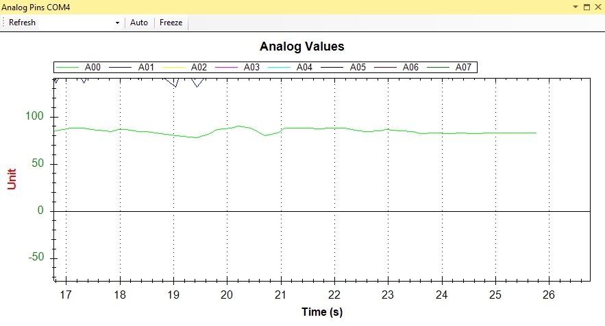
Problem is, the photo resistor is not giving off a steady output, even in a very steady light. For example, in daylight conditions in my room, the Analog Pin Monitor shows that the photo resistor output varies from around 70 to 80:

enter image description here

This problem becomes even more pronounced when light levels are low - I can't get a steady, accurate output. What can I do to fix this? Is it the way I'm wiring the thing? Let me know if you need any additional information, and I'll gladly provide it.

Thank you in advance.

\$\endgroup\$
7
  • 3
    \$\begingroup\$ "Is it the way I'm wiring the thing?" We don't know; you haven't shown us what you've done. \$\endgroup\$ Commented Mar 31, 2018 at 22:54
  • \$\begingroup\$ Sorry. Here's the photo: i.imgur.com/eWvw24L.jpg Photo resistor is connected to the positive rail on the breadboard, fed by 5V pin on the Arduino. Right after the resistor, a wire goes back to A0 pin on Arduino to get the output. Also, a 220 ohm resistor connects the photo resistor rail to the negative rail on the breadboard. Not sure why that is needed, but all tutorials specify this is a must. \$\endgroup\$
    – J R
    Commented Mar 31, 2018 at 23:00
  • \$\begingroup\$ You might try keeping it at a constant temperature. This may be difficult because current flowing through heats it up. \$\endgroup\$
    – glen_geek
    Commented Mar 31, 2018 at 23:34
  • 1
    \$\begingroup\$ even in a very steady light .... how do you know that for sure? \$\endgroup\$
    – jsotola
    Commented Mar 31, 2018 at 23:35
  • \$\begingroup\$ I tried all sorts of lights - natural (sun), different kinds of lamps... All of them make the photo resistor output jump around regardless. @glen_geek , how would I do that? \$\endgroup\$
    – J R
    Commented Mar 31, 2018 at 23:37

2 Answers 2

1
\$\begingroup\$

I don't know the reason for the instability of the output, but you would be in a better position to debug it if you understand a little more how it works.

What you have is a voltage divider formed by the photoresistor and 220ohm resistor. If the resistance of the photoresistor, at a given point, is R, the voltage measured by the Arduino is 220ohm/(220ohm+R).

If it is dark, R could be pretty high, say, 1Mohm, and the reading will be very low, on the order of 1mV. If it is bright, R will be much smaller, say, 1k, and the reading will be on the order of 0.9V.

It would be good to know what kind of a photoresistor you have to estimate its response at different lighting levels, but, without knowing it, I would increase the bottom resistor to 10K and see if you have any improvements.

First, it will increase your signal and, therefore, potentially improve the signal to noise ratio.

Second, it will limit the current at bright light, which could potentially cause excessive self-heating and instability (mentioned by glen_geek).

Based on the curve, I don't see any jumping. It would be useful to have more data and see if there is any obvious pattern.

I assume, you've blocked the sensor manually and saw the response changed (to make sure you are actually reading the output of the sensor - not some other floating pin.) If not, do it.

Not sure how the two LED's shown on the picture are used, but if, for some reason, you are turning them on, you may expect the output of the light sensor respond accordingly. In any case, it makes sense to unplug them, while you are debugging the issue with the sensor.

I would also check 5V: any noise on the 5V supply would directly translate to the noise in the sensor output (reduced by the divider).

Good luck with your project.

\$\endgroup\$
1
\$\begingroup\$

As noted in the comments, many factors can affect the level of the signal you're getting - minute changes in reflected light levels in the room, vibration of the photocell, thermal effects, electrical noise, etc.

You probably want to filter the input in software. I use a simple one-pole filter something like this; you can trade off response speed versus noise reduction easily.

static int value = 0;
int raw = analogRead( A0 );
value = ((value * 15) + raw) / 16; // very smooth but slow to respond
//value = ((value * 3) + raw) / 4; // noisier but faster to respond

This says, on each pass through the loop, to weight the previous result by a large amount and the new reading by a small amount, which smooths out small changes in light levels.

You also mentioned:

Also, a 220 ohm resistor connects the photo resistor rail to the negative rail on the breadboard. Not sure why that is needed, but all tutorials specify this is a must.

Without the fixed resistor, the 5V going into the photoresistor has nowhere to go other than the analog input pin, so you'd read 5V regardless of the light level. The variable resistance of the PR combined with the fixed resistor forms a voltage divider which puts a variable voltage on the input.

\$\endgroup\$
2
  • \$\begingroup\$ Thank you, I have a very similar code to smooth out the noise. It kind of works, but still doesn't help me to get accurate results, especially when light levels are low, and the photoresistor is only giving off 6 or 7. Is there any way to increase the sensitivity of the photoresistor, so it operates in higher number ranges in dim lightning conditions? \$\endgroup\$
    – J R
    Commented Apr 1, 2018 at 8:30
  • \$\begingroup\$ This Adafruit tutorial has some tips for optimizing the range: learn.adafruit.com/photocells/using-a-photocell — note that different photoresistors have greatly different resistance ranges so you’re going to have to do some math. \$\endgroup\$ Commented Apr 1, 2018 at 8:55

Your Answer

By clicking “Post Your Answer”, you agree to our terms of service and acknowledge you have read our privacy policy.

Not the answer you're looking for? Browse other questions tagged or ask your own question.