3
\$\begingroup\$

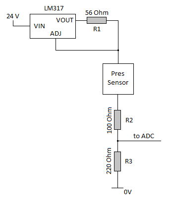
I'm looking at the 4-20mA circuit below and trying to understand it. For some reason I can't get this to click in my mind.

enter image description here

Pressure sensor is a Metallux ME751 with a supply voltage of 9..35 VDC and it outputs 4-20mA.

From my point of view (please correct me where I'm wrong!):

LM317 together with the R1 creates a current limiter at 1.25V / 56Ohm = 22.3mA. This current then goes through Pres sensor which change it based on the pressure. 4mA for its lowest point and 20mA for its highest point. The R2 resistor I don't understand the purpose of, but R3 will give a voltage to the ADC of 0.88V @ 4mA and 4.4V @ 20mA.

My questions:

  1. The pressure sensor needs a supply voltage of 9-35VDC, how do I know what voltage the pressure sensor gets? i.e. what is the voltage on the lowside of R1??
  2. What is the purpose of R2?
  3. If I removed the LM317 and just supplied 24V to the Pressure sensor I would know it got the voltage needed. Would it still produce a 4-20mA current based on the pressure or does it need a constant current to work?
\$\endgroup\$

3 Answers 3

1
\$\begingroup\$

The LM317 provides short circuit protection to the circuit, you can assume the voltage at the top end of the pressure sensor is more than 20V unless the pressure sensor tries to deliver more than about 22mA.

The 100 ohm resistor reduces the dissipation in the pressure sensor (may improve the accuracy a bit) and reduces the compliance range by a couple of volts (not necessarily a good thing, but as we'll see, it is not a problem). Typical bridge pressure sensors are fairly temperature sensitive and reducing the dissipation improves accuracy and stability (they are typically temperature-compensated, of course, but that compensation is generally static and does not correct as well for dynamic changes).

The 220 ohm resistor is the important one for accuracy. The voltage going into the ADC is 0.88 to 4.4V nominally (ignoring any loading from the ADC).


The pressure sensor is a loop-powered instrument, meaning that provided it has enough voltage across it to work it will adjust the voltage drop across itself to supply the required current. You say that voltage is a minimum of 9V. If you add up the drops I mentioned above 20V- 2V - 4.4V it still has 13.6V. Even if the 24V supply is a bit low there is plenty of voltage for the sensor.

Note that there should be some protection on the ADC (not shown) because a direct short of the input to +24 could allow almost 200mA to flow (assuming a 5V supply on the ADC), which is more than enough to cause a lot of damage. If there is a clamp on the ADC input, the 100 ohm resistor will limit the current, though it will probably burn up unless it is large (3.6W dissipation).

\$\endgroup\$
0
\$\begingroup\$

Q1: With a current limiter at the input, the voltage sensor will see the full voltage of the supply minus some small drop across the limiter. This is up to the current limit, after which the pressure sensor voltage would drop to whatever value needed to keep current at the limit.

Q2: Speculation since you don't provide details on the pressure sensor, but it may be that there is a maximum voltage drop spec on the sensor and with just 220 that voltage drop could be exceeded at low currents. Also could be for ADC short circuit protection, or even to allow a signal to be read without breaking the loop (is R2 a precision-value?).

Q3: You don't have a constant current, you have 4-20 MADC. So you need to rethink your constant-current premise. All of the current that flows through R3, R2, and the sensor goes through the current limiter, which is variable (again: 4-20 MADC).

Generally, current loop transmitters supply their signals through one or more devices, such as computer points, meters, paper recorders, etc. Since it is a loop, all devices get the exact same signal and without regard for variables such as signal wire resistance. These transmitters are VERY common throughout the industry,

\$\endgroup\$
2
  • \$\begingroup\$ Q2: Yes both R2 and R3 are 0.1% resistors What in the schematics above is considered the transmitter? The pressure sensor? Since for me the LM317 is the one generating the constant current source. \$\endgroup\$
    – RedSmolf
    Commented Apr 13, 2018 at 10:50
  • 1
    \$\begingroup\$ @Redsmolf The signal source is commonly called a transmitter. So, yes, your pressure sensor is the signal transmitter is this case. There are many types of transmitters and two common current signals, 4-20 MADC and 10-50 MADC. \$\endgroup\$ Commented Apr 16, 2018 at 9:47
0
\$\begingroup\$

I suggest you remove the LM317 and R1, and apply 24V directly to the + terminal of the pressure transmitter. It will draw as much current as it needs up to 20mA (typically an overrange condition is limited to 22~24mA).

R2 serves no purpose in a current source arrangement. The current is dependent on pressure and the compliance of the transmitter. Inserting R2 only steals from your compliance.

R3 is a burden or current sense resistor. It's there to turn the current signal back into a usable voltage. Left at the present value, your A/D will see voltages of (4ma * 220 ohms = 0.88V) at the lowest pressure and (20mA * 220 ohms = 4.4V) at the highest pressure. The resulting offset and span can be calibrated out in software.

Typically, the sense resistor is sized to produce 1-5V or 2-10V for use with A/Ds, for both convenience and to maximize the range of the A/D.

\$\endgroup\$

Your Answer

By clicking “Post Your Answer”, you agree to our terms of service and acknowledge you have read our privacy policy.

Not the answer you're looking for? Browse other questions tagged or ask your own question.