It's a very cheap way to create a speed controller that has a predictable voltage drop without the same level of current limiting created by a resistor based voltage divider.
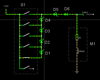
The switch puts a variable number of diodes in series to create a combined voltage drop.
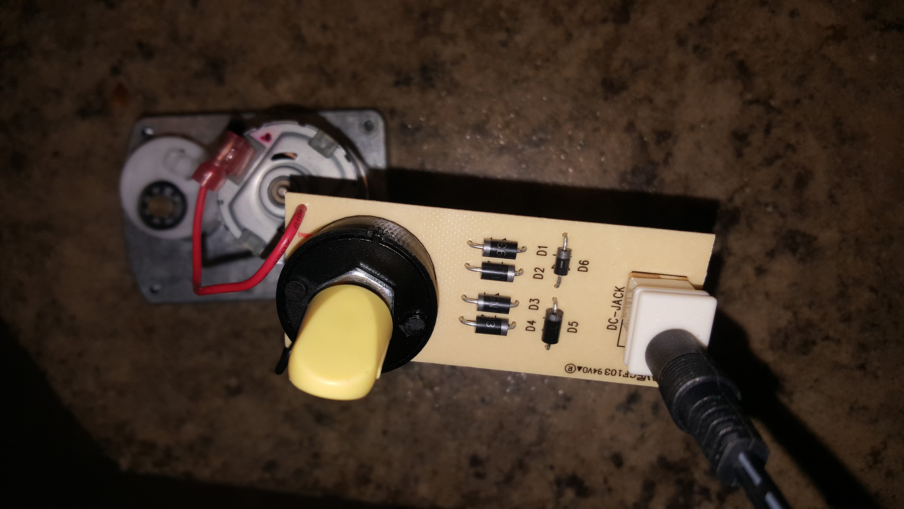
The larger diodes (D1-D5) seem to read "1N593" from what I can make out. If that's correct, they would be zener diodes in the forward biased mode. That family of zeners have a 15-39V zener voltage and a 1.5V forward voltage. They're using the 1.5V forward voltage to limit the motor input.
The smaller diode (D6) is probably a standard rectifying diode. Hopefully one with a relatively high reverse voltage, because they don't seem to have anything else to deal with back EMF when that motor stops. This would add another 0.6V voltage drop.
If that's all correct, you should expect to see about 10V on high and about 4.5V on low with 1.5V increments between. Regardless of exact numbers, that's the basic theory of operation.
It's not very efficient and is only useful for small increments, so I would not be trying to adapt this for larger motors.
Here's a simulated version of the circuit (based on my assumptions for exact parts used and with some equivalent components for the rotary switch and motor)


