Consider I have a 2.048 V reference voltage, for example, I build this voltage with an REF191. This IC has only 10 mA output current. How can I boost this current to 200 mA? Is there any better way to build an accurate 2 V reference with 200 mA output?
-
1\$\begingroup\$ How much accuracy do you require? \$\endgroup\$– Tom CarpenterCommented May 19, 2018 at 11:25
-
\$\begingroup\$ One easy way is to add an op-amp buffer after your reference. Might be overkill. \$\endgroup\$– ReinderienCommented May 19, 2018 at 11:27
-
\$\begingroup\$ 2mV, maintain the accuracy of ref191 \$\endgroup\$– AqaRashidCommented May 19, 2018 at 11:29
-
\$\begingroup\$ "Typical application circuits" section of this may give you some advices. \$\endgroup\$– Long PhamCommented May 19, 2018 at 11:50
-
4\$\begingroup\$ You want 10m\$\Omega\$ output resistance over what frequency? Just at DC? Just source or source/sink? Half an inch of 20mil 1oz trace will be more than that so you likely need feedback from the remote points where you want the 2.048V and 0V potential difference to exist. In this case 'remote' could be just a few mm. \$\endgroup\$– Spehro 'speff' PefhanyCommented May 19, 2018 at 13:50
1 Answer

simulate this circuit – Schematic created using CircuitLab
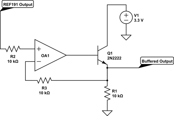
This should do the trick. Be sure to use an op amp that has a max output offset voltage of 2mV. This may also be unstable, so don't use it for mass production before you do some analysis.
edit: I was bored so I made a full design.
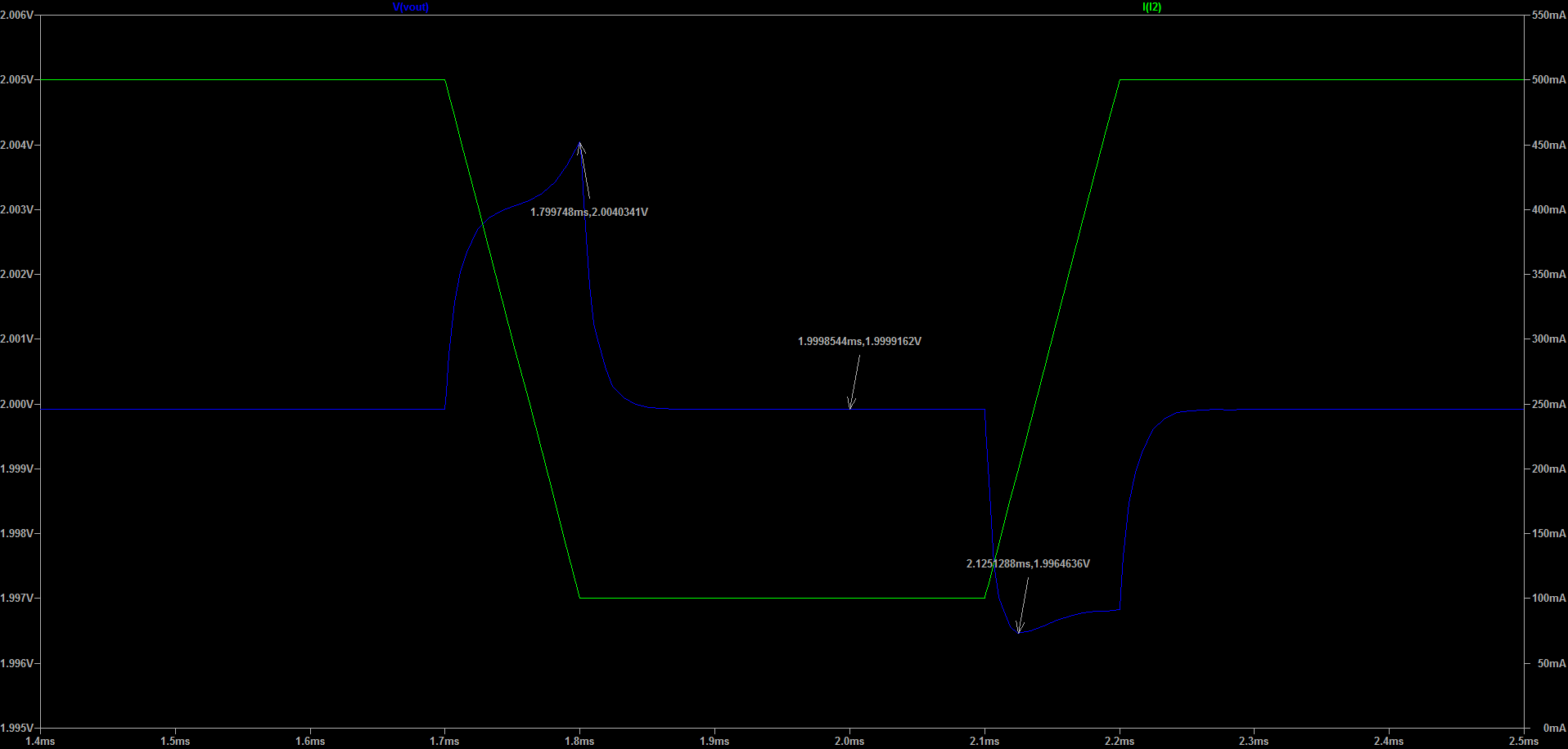
(100mA - 500mA load step)
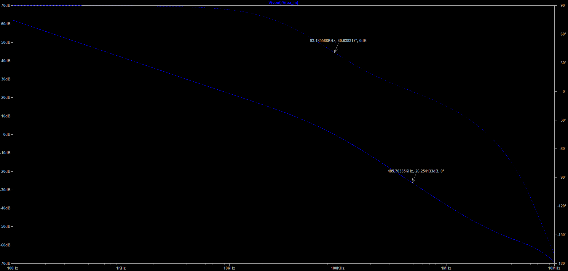
Phase margin and gain margin. I targeted a crossover frequency of 100kHz (I have no idea what your requirements are, but a design at 1MHz crossover frequency is probably possible using this op amp.)
-
\$\begingroup\$ Just to add but not to complicate the question: if you have oscillation issues, you can add a "fast path" feedback path from the opamp output to the inverting input with some low value caps. \$\endgroup\$ Commented May 19, 2018 at 15:01


