0
\$\begingroup\$

My knowledge of electronic components is limited, what training I have received comes from a 6-week course I took in the Army in 1984. So, yes I am in over my head but not on my own volition. I do have a young guy, Ken, with a degree of some sort related to electronics helping me.

The problem

I have a simple 12v DC motor and two SPDT Relays. I need to wire the relays so the motor will go up and down using momentary switches. There is no diode in any of the components.

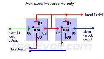
I first followed the diagram pictured below that Ken sent me. I wired the rocker switch so that it received its power straight from the fused 12v line; I then placed a diode between the two motor leads. Nothing visible happens.

Actuators/Reverse Polarity

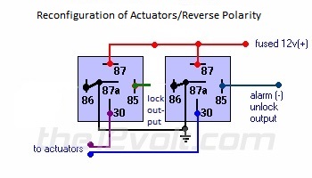
After that did not work, Ken had me switch some lines as you can see in the diagram below.

Reconfiguration of Actuators/Reverse Polarity

That kept blowing the diode.

Now Ken thinks I need two diodes and the diodes need to be connected across pins 85 & 86.

But, Ken also keeps trying to tell me the motor is bad.

The motor is fine. If I straight wire the motor it goes down, if I switch the connections and add the diode the motor goes up.

Please Help!

\$\endgroup\$
5
  • 1
    \$\begingroup\$ Your circuit would be much easier to understand if you used normal relay symbols that clearly show the relay coil and contact arrangement, rather than those boxes with cryptic numbers for the terminals. Also, show the motor and diode connections. \$\endgroup\$ Jul 23, 2018 at 15:43
  • \$\begingroup\$ Your diagrams just show the pin numbers on the relays, but we can't tell from that which pin is which. \$\endgroup\$
    – Simon B
    Jul 23, 2018 at 15:43
  • \$\begingroup\$ Maybe you need something like this: electronics.stackexchange.com/questions/149885/…. Your relay pin diagrams are pretty confusing, try simpler representative contact symbols. \$\endgroup\$
    – Andy aka
    Jul 23, 2018 at 15:44
  • \$\begingroup\$ "I then placed a diode between the two motor leads." Now, that would blow either a fuse or a diode. What does "to actuators" mean? I thought you have only one motor. How do you use rocker switch? Is it to simulate those "alarm outputs"? Because outputs marked with (-) and you connect rocker switch to 12V. Also rocker switch is definitely not "momentary". It would really help if you show more of your circuit. \$\endgroup\$
    – Maple
    Jul 23, 2018 at 17:16
  • \$\begingroup\$ What goes up and down as the motor rotates CW and CCW? Is there gravity load to force rotation? gear reduction, or some brake? Just asking in case you need to reconsider this design. Surge currents need to be considered. \$\endgroup\$ Jul 23, 2018 at 17:20

1 Answer 1

1
\$\begingroup\$

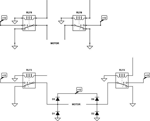
I will translate your automotive relay nomenclature into our electronic nomenclature:

  • 85 and 86 are coils
  • 87 is N.O. (normally open)
  • 87a is N.C. (normally closed)
  • 30 is COM (common)

2nd diagram:

schematic

simulate this circuit – Schematic created using CircuitLab

\$\endgroup\$
1
  • 1
    \$\begingroup\$ Thank you for the translation and your answer. I will be ordering a Bridge today. \$\endgroup\$
    – vmblink
    Jul 23, 2018 at 16:03

Your Answer

By clicking “Post Your Answer”, you agree to our terms of service and acknowledge you have read our privacy policy.

Not the answer you're looking for? Browse other questions tagged or ask your own question.