5
\$\begingroup\$

Often the IC datasheet recommends putting a ferrite bead before AVCC pin. First I started wondering if I don't need a flyback diode but than I realized that capacitor is probably able to absorb the excess current.

For back of the napkin calculations I assumed that ferrite bead is an inductor so total energy stored before switching off is \$ CV_0^2 + LI^2 \$.

When the power is cut off all energy needs to be stored in capacitor so energy now is \$ CV_1^2 \$.

So if I want the voltage not to be above some \$V_t\$ I need to have capacitance of:

$$ C_{min} = \frac{LI^2}{V_t^2 - V_0^2} $$

So assuming \$L = \frac{X}{2 \pi f}\$, \$300\,\Omega\ @\ 100\,\mathrm{MHz}\$ ferrite bead, \$I = 20\,\mathrm{mA}\$, \$ V_t = 5\,\mathrm{V}\$, \$ V_0 = 3.3\, \mathrm{V}\$ it gives \$C_{min} \approx 14\,pF\$. Other way round standard \$ C = 0.1\ \mu\mathrm{F}\$ capacitor gives swing of \$0.3\,\mathrm{mV}\$.

Is this reasoning correct? I've made a few spherical cow assumptions and I'm just a beginner.

\$\endgroup\$
4
  • 2
    \$\begingroup\$ Why are you expecting to see a flyback diode? Most ferrite beads do not behave much like an inductor. They are lossy at high sfrequencies. If your bead supplier provides a plot of impedance against frequency this should be obvious. \$\endgroup\$ Commented Jul 27, 2018 at 8:01
  • \$\begingroup\$ You've worked out the inductance from the impedance at 100MHz, but switching off the power done at DC. At DC the impedance of a ferrite bead is just a few Ohms, most of which is resistance anyway. Check the impedance v frequency charts. \$\endgroup\$
    – Steve G
    Commented Jul 27, 2018 at 8:02
  • \$\begingroup\$ @WarrenHill Because I expected ferrite bead to be kind of like inductor. \$\endgroup\$ Commented Jul 27, 2018 at 16:32
  • \$\begingroup\$ Your assumptions about the shape of the cow do show excellent understanding of typical farm-property constraints in cow-gates. \$\endgroup\$ Commented Jul 29, 2018 at 5:39

1 Answer 1

6
\$\begingroup\$

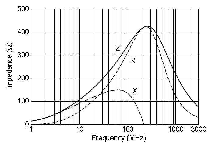
A typical ferrite bead impedance graph: -

enter image description here

This one peaks around 400 ohms and as you can see the impedance is virtually purely resistive. These are the eddy current losses in the magnetic material. Inductance has dropped off to virtually negligible amounts.

But it does have inductance at low frequencies (and very few losses) so it's worth calculating. At 1 MHz the losses can be assumed zero but the reactance is about 15 ohms (an estimate). So this provides us with the inductance i.e. L = \$X_L/2\pi F\$ = 2.4 uH.

At 20 mA this is inductance holds about 0.48 nJ of energy.

But, given that when you switch your supply off the 20 mA current flowing through the inductor gets benignly absorbed by power supply capacitors on the main power rail I don't think you need to worry.

\$\endgroup\$

Your Answer

By clicking “Post Your Answer”, you agree to our terms of service and acknowledge you have read our privacy policy.

Not the answer you're looking for? Browse other questions tagged or ask your own question.