2
\$\begingroup\$

I want to design a dc-dc boost converter and manage power (MPPT) for an ultra-low power fuel which contains input voltage < 1 V and input current < 500 uA. if I choose simple boost converter, I will have problem with inductor design because low input current (about 500 uA) will cause extremely high inductor.

Here is the formula for calculating inductor for simple boost converter [L= (Vin*D)/(fs*0.3*iL)]

I need to choose high freq and high L that means an inductor with more than 10 mH inductance and work in 5 MHz freq. (we don't have inductance in this spec) what should I do for power managing of this ultra-low fuel?

\$\endgroup\$

2 Answers 2

2
\$\begingroup\$

I will have problem with inductor design because low input current (about 500 uA) will cause extremely high inductor.

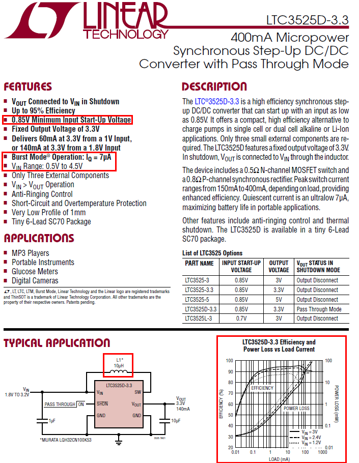
No, this is not the case in burst mode operation. For example the LTC3525 specifies that the burst mode quiescent current is typically 7 uA and if you look at the picture below you can see this.

enter image description here

I'm not saying this device is perfect for your needs but it does tick several boxes such as reasonable efficiency on light loads (maybe as low as 100 uA), low start-up voltage and an inductor value of 10 uH or thereabouts.

The formula you used to determine inductance is not when operating in burst mode. The capacitor at the input soaks up the energy delivered by the power source and this means your quiescent average current from the power cell can be very low providing your output current (boosted output) average load current is also very low.

\$\endgroup\$
4
  • 1
    \$\begingroup\$ I appreciate your response. I don't agree with ur opinion because : the peak current in Inductor ( Iin ) will obey this formula in every boost converter [ Ipeak=(VinD)/(fsL) ]. so we can use very low Duty Cycle (for example 1%) to reach low quiescent current (7 uA in datasheet) but we cant Power manage with 1% Duty Cycle ... if I increase Duty Cycle, I will sink more current from my Fuel cell ( i can't do more than 300 uA like I said before ) I think quiescent current report in an IC data sheet is a trick. it cant Power manage in this mode ... \$\endgroup\$
    – A.Z
    Commented Jul 29, 2018 at 11:04
  • \$\begingroup\$ @A.Z you forget the capacitor at the input to the circuit. It'll accumulate energy delivered at low current levels and sustain 30 mA (or so) through the inductor for short periods of time. The inductor peak current is >> than your fuel cell average current but that is not what is important. I = C dv/dt and at 0.5 mA and 1 uF the voltage rise is 500 V/sec. This is countered by the pulse of inductor current (say 30 mA for 1 us) and reduces the capacitor voltage by 30 mV for each 1 us. You just have to ensure your load power is no more than about 50% of input power. \$\endgroup\$
    – Andy aka
    Commented Jul 29, 2018 at 11:33
  • \$\begingroup\$ can you please give me a simulation about what you say? \$\endgroup\$
    – A.Z
    Commented Aug 12, 2018 at 8:58
  • \$\begingroup\$ @A.Z not5 really but if you have a simulator you can do this yourself. Sims are free these days like micro-cap student edition so it wouldn't take too much setting up. If you do this you can post a new question if the sim isn't giving you the results and get more front-line help from other folk as a spin-off. \$\endgroup\$
    – Andy aka
    Commented Aug 12, 2018 at 9:41
0
\$\begingroup\$

The way it works is that you charge a capacitor from the fuel cell (FC). When the capacitor has enough charge (voltage) then you start a single flyback cycle. This is a discontinuous flyback convertor.

The convertor inductor/current is independent of the FC current. The on time (charging the inductor) is fixed, and can be anything from less than a micro second to 100us. Because the voltage you start at is fixed, inductance is fixed, then using a fixed on time, means a predetermined current will flow.

To keep on the MPPT point, you don't want to discharge the cap too much with the flyback pulse, so design it for (say) 10% drop in voltage during the flyback cycle.

Aside from using a dedicated chip, it is very easy to do this with a small micro like a PIC.

 repeat {
   if Vcap>Vthreshold {
     SwitchOn;
     delay1us;
     SwitchOff;
    } else { 
      SnoozeinLowPower; 
    }
 }

For example this arrangement has 10mA inductor current per 1us on time. Try using the simulator and changing the values. (I am using a CLK for the fixed width pulse). You will see that a 470nF cap sees 1 pulse every 50us. You could have a 100uF cap, and a burst of pulses every 10ms, or a 0.2F supercap with pulses every 20seconds. (and sleep between)
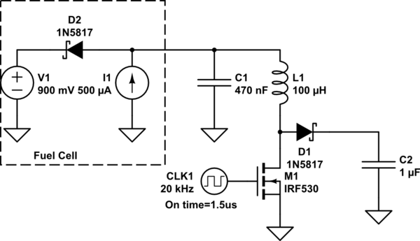
schematic

simulate this circuit – Schematic created using CircuitLab

\$\endgroup\$
1
  • \$\begingroup\$ I appreciate your response. I will check ur idea and leave a comment if I get an answer. \$\endgroup\$
    – A.Z
    Commented Jul 29, 2018 at 11:00

Your Answer

By clicking “Post Your Answer”, you agree to our terms of service and acknowledge you have read our privacy policy.

Not the answer you're looking for? Browse other questions tagged or ask your own question.