5
\$\begingroup\$

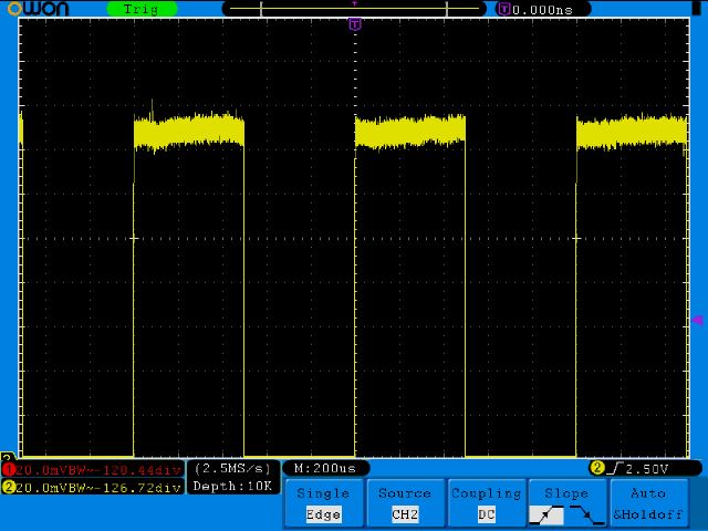
I just received an Owon SDS7102v 100 MHz oscilloscope. After checking out the menu structure I decided to compensate the probes. Channel 2 seems to work fine with either probe.

[Channel 2 properly compensated, 20mV/div] enter image description here

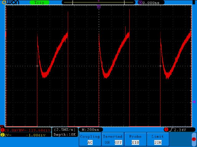
Channel 1 on the other hand is a different story.... There is quite the hook across the top portion of the square wave. I get the same result using either probe. Any ideas what is causing this? Is the input bad? Is there anything I can do to try and fix this issue?

I have a warranty but I just received the scope so I'm not too excited about sending it back to China for repair....

[Channel 1 probe compensation, 20mV/div] enter image description here

\$\endgroup\$
1
  • \$\begingroup\$ By the way, I have the non v version of that same scope and my channel one output looks same as your channel two output. \$\endgroup\$
    – AndrejaKo
    Commented Aug 27, 2012 at 10:54

2 Answers 2

3
\$\begingroup\$

Somethings not quite right there.

I have the 200MHz SD8202 which has the same manual so I assume the procedures are the same. It has a 5V pk-pk compensation output. I'm guessing you have adjusted the vertical position to zoom in at the top of the waveform.
I just tried this and I get similar to your top picture but with a bit less noise (did you connect the ground clip too? Was it bandwidth limited to 20MHz like the second waveform?)

All I can think of trying right now is running the self calibration routine (remove probes, press "Utility" button, press "Function" (H1 button), choose "Adjust" with "M" knob, press "Self Cal" (H2 button)
Let this complete (couple of minutes) and try the probe compensation again. Let us know how it goes.

EDIT - What do you get with all the waveform on the screen? (e.g. 1V/div)
It's possible the front end is slightly different in your model (or conditions/part tolerances are different), and it's at the limit of the vertical amplifier as Zebonaut proposes.
I'd also try a divider on the compensation signal to make it so the full waveform is on the screen at 20mV/div, just in case it's a problem specific to that gain setting.
At 5V pk-pk, to bring it down to say, 100mV pk-pk you need a 50:1 divider. Something like 50k and 1k will get "close enough" (98mV pk-pk) Or use a potentiometer and just adjust visibly.
If it still looks the same like this then I would say there is a problem.
\$\endgroup\$
8
  • \$\begingroup\$ Yes, I had the vertical position we'll below the display area so I could see the top of the square wave with the 20mV scale. I did connect the ground clip on both screen captures above and both signals were BW limited to 20MHz. I tired the self cal a few times now with no success (e.g. no change in the "hook" on channel 1). I performed the self cal under a few conditions, directly after powering the scope on and after the scope had been running for 25-30 mins. Seems like this would have been noticed at the supplier's facility during some form of acceptance test.... \$\endgroup\$
    – Ryan B.
    Commented Aug 26, 2012 at 19:18
  • \$\begingroup\$ @RyanB. - see edits - try it on 1V/div and also the suggested 20mV/div but with 100mV pk-pk signal. Post the links to screenshots if you can (we'll edit them into your question) \$\endgroup\$
    – Oli Glaser
    Commented Aug 26, 2012 at 20:32
  • \$\begingroup\$ I used a voltage divider to give ~100mvp-p and it does look quite different and there is not the 80mV deviation across the top of the signal as before Channel 1 100mvp-p It was really hard to make any adjustments because the noise at this level is everywhere and any wire/pin was acting as a antenna. But I was able to shield it enough to get a screen shot. After making the adjustment and looking at the signal full scale there is still a slight slant. Channel 1 full scale \$\endgroup\$
    – Ryan B.
    Commented Aug 26, 2012 at 22:13
  • \$\begingroup\$ Maybe I am being too picky.. There is a definite difference between channel 1 & 2 but still useable. I would think the input channels would be electrically the same so if I use the same probe on both inputs and get two different results I have to believe one of them has a slight difference. Does anyone know what a DSO input circuit consists of? I know there is a RC circuit used to match the impedance of your probe and some voltage scaling then probably onto an A/D but the only thing I found online was basically a block diagram. I'm wondering what in the input circuit would cause this. \$\endgroup\$
    – Ryan B.
    Commented Aug 26, 2012 at 22:21
  • \$\begingroup\$ It's possible the front end parallel compensation capacitors (usually trimmer caps) are slightly out. The front end of a high speed DSO is a tricky thing to get spot on. A basic example circuit is the DSO Quad, note the trimmer caps C1A-C6A. If these are slightly out it can cause big issues with frequency response. I have had mine apart (funnily enough mine had an issue too - my fan was noisy so I got them to send me a new one and fitted it myself) and it's quite involved... \$\endgroup\$
    – Oli Glaser
    Commented Aug 26, 2012 at 22:36
1
\$\begingroup\$

At 20 mV / div and with a signal of 5 V pkpk, you may be overdriving what used to be called the vertical amplifier in analog scopes, and what is now the front end or the ADC. You may be seeing a mixture of a probe that is compensated not quite right and your input stage trying to recover from being overdriven.

The reason why I use analog scope terminology is that these scopes tended to be more forgiving when being overdriven.

To be sure, you could try the following settings:

  • Coupling: DC

  • BW Limit: OFF

  • Y: 1 V / div (or anything else that will put the entire waveform onto the screen)

When compensating your probe, no huge vertical deflection (V / div) is needed. Try to adjust the probes when you have the entire signal on your screen.

\$\endgroup\$
5
  • \$\begingroup\$ It still looks like there is a dip in the top of the square wave and if I adjust the probe until the line is straight the square wave has a rounded edge. link link On Channel 1 while making the adjustment the entire line (top of wave) moves and at a certain point vertically about 3/4 of the way across the top of the signal the line stops moving as it there is some limit. The line to the left of this area continues vertically causing the hook. \$\endgroup\$
    – Ryan B.
    Commented Aug 26, 2012 at 20:26
  • \$\begingroup\$ Channel 2 does not exhibit the same characteristic while making the adjustment. Only about the last 1/4 of the entire line (top of wave) moves and the rest of the square wave is perfectly horizontal to start with and is not effected by the adjustment. Channel 2 has very sharp edges once the compensation is complete. Channel2 \$\endgroup\$
    – Ryan B.
    Commented Aug 26, 2012 at 20:31
  • \$\begingroup\$ I agree that the pictures you link to in your comment look less than ideal. Another simple test to find out if the problem is caused by the input channel or by the probe: Switch your probes (the one that was on Ch.1 to input 2, the one that was on Ch.2 to input 1). If the problem migrates with the probe, there may be something wrong with the probe. If the problem sticks to Ch.2, there may be an issue with the scope itself. One more test, if you have the devices: Use a good function generator, terminate your scope input with a 50 Ohm resistor, and check the signal quality. \$\endgroup\$
    – zebonaut
    Commented Aug 27, 2012 at 6:52
  • \$\begingroup\$ I used the same probe throughout all of the testing performed. Unfortunately I don't have a function generator. Although it is on my list of things to acquire (eventually). \$\endgroup\$
    – Ryan B.
    Commented Aug 28, 2012 at 0:27
  • \$\begingroup\$ Correction to that statement I used the same probe for the screen captures but I tried three different probes and they all showed the same issue. \$\endgroup\$
    – Ryan B.
    Commented Aug 28, 2012 at 2:38

Your Answer

By clicking “Post Your Answer”, you agree to our terms of service and acknowledge you have read our privacy policy.

Not the answer you're looking for? Browse other questions tagged or ask your own question.