Note: this is part of a larger question which I was asked to separate into subquestions. Other subquestions: 1 and 2
I am using a passive RC integrator to measure the induced magnetic flux density in a toroidal transformer made of Nanoperm (additional datasheets here and here). This method is outlined here but involves using an op-amp integrator rather than a passive one. (I tried building the active one but it was giving me issues.)
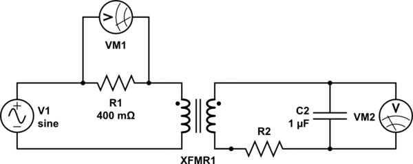
The circuit diagram of my proposed circuit is given below:

simulate this circuit – Schematic created using CircuitLab
The signal generator is connected to an audio amplifier capable of driving large currents. I'm driving the transformer with sinusoidal signals at 50 Hz, 350 Hz, and 380 Hz, and I had initially set R2 to be 5 kOhms. According to comments on the previous larger question I had posted, this value of R2 is too small (cutoff frequency is too high). I increased R2 to 10 kOhms, 27 kOhms, and 37 kOhms. The table below summarizes the cutoff frequencies and gains for input frequencies of 350 and 50 Hz, which were used in these experiments:

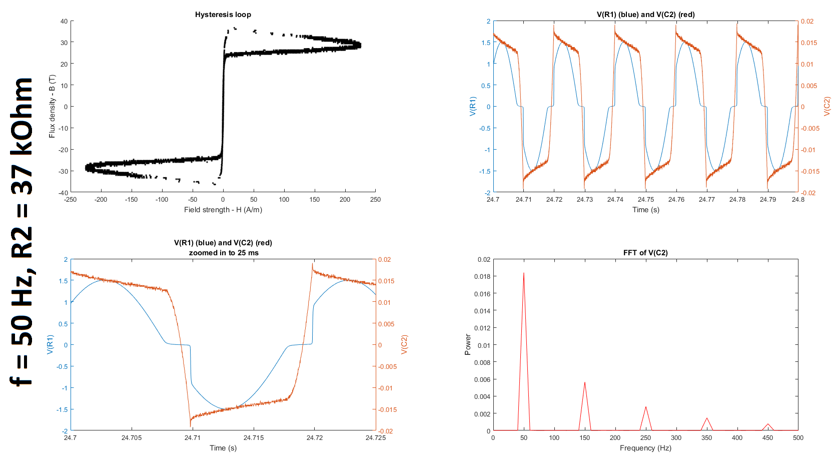
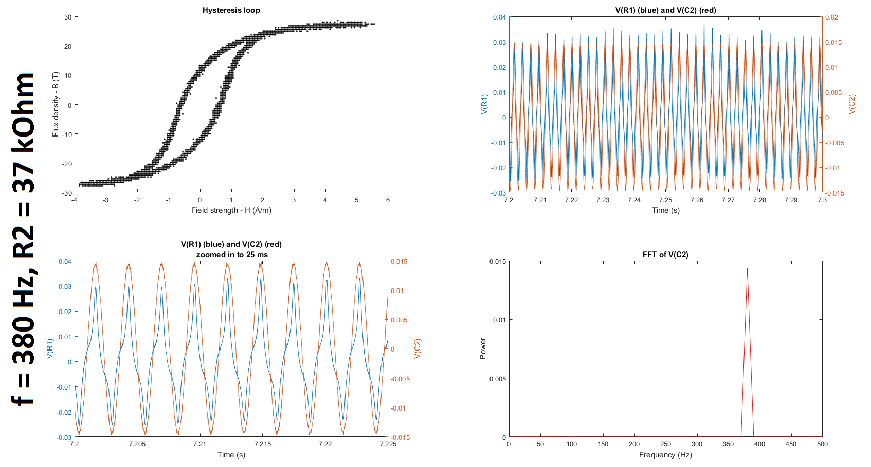
The first subplot in the two figures below show hysteresis loops measured at an input frequency of 50 Hz and 380 Hz for R2 = 37 kOhm. (I tried additional input frequencies and values of R2, and details of my complete experiment can be found in my original question.) Additionally, the raw voltages VM1 (V(R1)) and VM2 (V(C2)) are plotted in the second and third subplots, and the Fourier transform of V(C2) is plotted in the fourth subplot.
While my results look slightly better after changing R2, they still do not match the results reported on the datasheets. (Q1) It is unclear to me why we increase rather than decrease R2 because the cutoff frequency of the filter only gets smaller as we increase the resistance. If someone could clarify for me why this is helpful, I would appreciate it. (I understand that the higher the resistance, the lower the cutoff frequency; and the lower the cutoff frequency, the greater the window of integration since (1) the time constant gets larger and (2) a larger time constant implies a larger window over which the signal is smoothed, which is what is required for only lower frequencies to be passed. I'm just not sure why reducing the gain of the frequency of interest, which is much higher than the cutoffs tabulated below, is a good thing in this case.) (Q2) Furthermore, is it even reasonable to use any gain other than 1 unless we compensate for it when we calculate the field strength and/or flux density from the measured voltages?


