0
\$\begingroup\$

In a data acquisition system, a single ended earth grounded daq board has inputs from many force transducers and some transducers types.

Daq basically has a common ground for all inputs and multiplexes the inputs.

Below is a simplistic model od this application: enter image description here
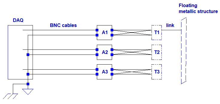
My question is only about a peculiar observation.

If you look at the diagram above, when any of the force transducer's shield(T1 as an example in the diagram) touches a large floating metallic frame nearby(an aluminum frame where many servos mounted on it but the system is OFF); when any of the transducer's shield touches to this frame, that particular channel picks up large amount of 50Hz and its harmonics noise. But not the other channels. I observe this from the daq software.

I thought if it were a ground loop this noise would appear on all channels, but since it appears only on the channels which is in contact with the frame I thought it cant be ground loop? Does that mean the frame picks up the 50Hz noise through the air?

What can be said about the coupling way of the noise knowing that it only appears on the channel which is in contact with the frame even though all channel grounds are common at the daq side?

Edit:

enter image description here

\$\endgroup\$
1
  • \$\begingroup\$ This is why vinyl music turntable/tonearm systems have the FIFTH wire, the braided GROUND wire, to tie the turntable/tonearm to the audio preamplifier Ground. (the other 4 wires are the twisted-pairs for Left and RIGHT audio channels, from the cartridge). \$\endgroup\$ Commented Feb 11, 2019 at 14:42

1 Answer 1

2
\$\begingroup\$

Does that mean the frame picks up the 50Hz noise through the air?

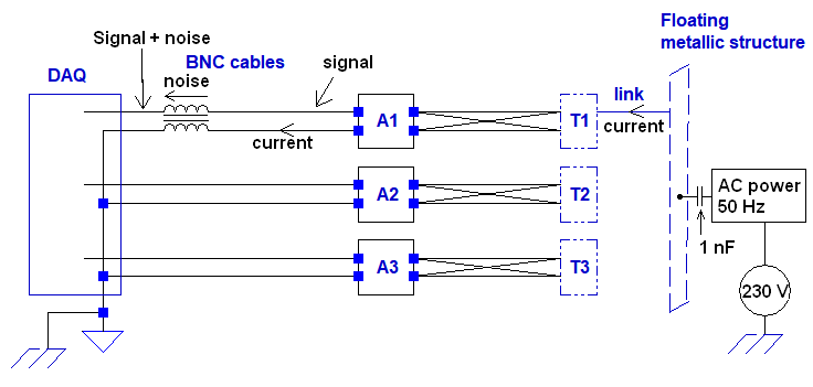
Yes, your floating metallic structure is a source of 50 Hz due to capacitive coupling to 50 Hz cables and this structure can source current if grounded.

Single ended inputs use a ground wire and an input wire. The 50 Hz from the structure coupling forces a current to ground through the grounded wire and will generate (due to Faraday's law of induction) an interference voltage on the closely coupled input wire. So you get signal + interference: -

enter image description here

If you used a balanced input, the noise would appear identically on both balanced inputs and would become theoretically zero at the input amplifier's output node (due to cancellation). This is because balanced inputs have the same impedance to ground and behave identically when an interfering signal is present.

\$\endgroup\$
4
  • \$\begingroup\$ Thanks; first I tried to model this in LTspice following your capacitive coupling hint. See my edit here: i.sstatic.net/CPbHS.png T1 and T2 are transducers which in real they share the same grounds. But as I have written when T1 touches the frame I see noise only on the DAQ channel for T1 not on T2. But in my model if I couple the "tip" from the capacitvie coupling the noise appears on both channels. Im scratching my hair still couldnt model this properly. Hope you can help. (The coupling should effect only the measurement on that frame touching transducer not all the channels) \$\endgroup\$
    – user1245
    Commented Oct 9, 2018 at 12:58
  • \$\begingroup\$ I’ve explained the phenomena, please don’t expect me to debug your model. You need to use coupled inductors to model this correctly. \$\endgroup\$
    – Andy aka
    Commented Oct 9, 2018 at 16:14
  • \$\begingroup\$ I understand what you mean now, The shield/case is picking through capacitive coupling and couples it to the unbalanced line through magnetic coupling. \$\endgroup\$
    – user1245
    Commented Oct 10, 2018 at 20:27
  • \$\begingroup\$ Correct. Good old Faraday. \$\endgroup\$
    – Andy aka
    Commented Oct 10, 2018 at 22:02

Your Answer

By clicking “Post Your Answer”, you agree to our terms of service and acknowledge you have read our privacy policy.

Not the answer you're looking for? Browse other questions tagged or ask your own question.