I have made a circuit with two (3v) LEDs in series. Connected to a 5v supply from an adapter with usb. (1.5Amp) I belive in series circuit each led gets around 2.5v which was enough to light them. However they both burned out after a short while. With Ohms low it would mean i dont need a resistor in this circuit! But now i think I should need one. Confused as to which resistance to choose and how to place this in this series circuit!?!!!? Please help I know its might be a very basic question!
-
1\$\begingroup\$ If you had two LEDs in series, each with a forward voltage of 3V, connected to a 5V powersupply, then they would not light up, and certainly not burn out. \$\endgroup\$– JRECommented Oct 21, 2018 at 17:40
-
5\$\begingroup\$ @jre forward voltage is a scale and not a single value. They would light up at a lower forward current and voltage... \$\endgroup\$– PasserbyCommented Oct 21, 2018 at 18:14
-
1\$\begingroup\$ It is very difficult to be SURE what went wrong with your circuit. But one possibility is that as the LED's warmed up, the current increased, and they went into thermal runaway. With LED's, a small voltage change will typically give rise to a large current change. For this reason, designers normally try to drive LED's with some approximation of a current source. I agree with others that it would probably be best to put the LED's in parallel and drive each one with its own current source. \$\endgroup\$– user57037Commented Oct 21, 2018 at 19:54
-
\$\begingroup\$ The current source could be as simple as a resistor in series with each LED. Or you could use a fancier source based on transistors or integrated circuits. Hard to say without asking a lot more questions. \$\endgroup\$– user57037Commented Oct 21, 2018 at 19:57
4 Answers
Red,yellow leds usually need only 1.8-2V to glow depending on the led. so you need to use a resistor in series based on your brightness requirements. this forward voltage needed depends on the led.
for red, I suggest around 20mA current which will give you a resistance of 50ohms.
-
3\$\begingroup\$ On a lot of these smaller battery powered LED applications, the design relies on the internal resistance of the batteries to allow the terminal voltage to drop to a point where the current through the LED isn't excessive. It's a really cheesy way of doing it, last year I bought a couple of flashlights that had boost converters that run off a single 1.5V AA cell, it's amazing how much more battery life they have, while not suffering the rapid drop-off in light output that the 3 AAA cell versions I had before. \$\endgroup\$– Phil GCommented Oct 21, 2018 at 17:38
-
2\$\begingroup\$ @Misunderstood What on earth is the 'natural Vf' of an LED. Please define. \$\endgroup\$ Commented Oct 21, 2018 at 19:02
-
2\$\begingroup\$ @Misunderstood LEDs are a form of diode and are NOT a current driven device. They have V-I characteristics so you cannot separate one from the other. The most important characteristic of the device that you don't want to exceed is power capability. Both V and I are elements in this limitation. \$\endgroup\$ Commented Oct 21, 2018 at 20:17
-
1\$\begingroup\$ @Misunderstood Of course I can have it both ways! The LED burned out because it's power capability was exceeded, the current flowing at this failure point is the result of being at a particular point on the V-I curve. V*I=P, surprisingly simple. The wire bonds on the LED are probably able to support many hundreds of mA and the LED leg wires 10's Amps so are unlikely to be the cause of failure. From my first comment, if the voltage is not too high to cause sufficient current to flow that results in the power rating being exceeded ...the LED will be fine. Exceed the power rating and Poof. \$\endgroup\$ Commented Oct 21, 2018 at 20:48
-
1\$\begingroup\$ Small change in voltage results in a large change in current. THUS, it is standard practice to drive LED's with something approximating a current source. Everybody knows this. Sometimes the approximation is just a resistor in series with the LED. Sometimes it is more fancy. If there is no stable voltage available, it is better to use a slightly more fancy current source. \$\endgroup\$ Commented Oct 22, 2018 at 22:59
They are almost certainly not '3V LEDs'. LEDs can operate over a variety of voltages so long as the current through them is kept in check.
A resistor is needed to do that.
Your LEDs most likely have a forward voltage of 2.1V and want around 20mA to be at their brightest. Exceeding 30mA would probably cause them to burn out.
So let's stick them in series with your 5V supply and see what resistor we need:
Ohms law: V = I x R can be rewritten as R = V / I
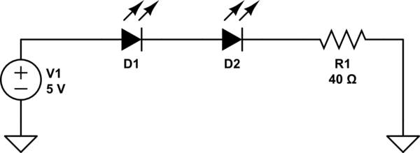
Our voltage is 5 - 2.1 - 2.1 = 0.8V and if we want maximum brightness our current is 20mA.
So R = 0.8V / 0.02A = 40 Ohms.
Thus you should build (increase R1 to reduce brightness):

simulate this circuit – Schematic created using CircuitLab
An LED should, in most cases, have a device to limit the current.
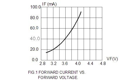
An LED does not have a single specific forward voltage (Vf). There is min, typ, and max. The there is a curve based on the amount of current flowing through the LED.
This is the I-V curve for a 3.2 Vf, 20 mA LED Cree 5-mm Round LED C512A-WNS/WNN
This I-V curve is made by measuring the Vf as the current is increased. Vf is a function of current. You cannot reverse this to where current is a function of voltage. You cannot apply a voltage and have a predictable current.
So when you connect directly to a voltage source, you will have no idea how much current is flowing. You are forcing the LED to a fixed voltage rather than allowing it to operate at the natural I-V point putting stress on the LED causing it to fail or decrease its lifespan.
When two LEDs are in series the current through each LED must be the same. Driving a string of two 3V LEDs with a voltage source, the source voltage will be divided between the two LEDs. It's not likely the characteristics of both LEDs will ever allow the LEDs reach a point of equilibrium where both can operate harmoniously at the same current.
No two LEDs have the exact same I-V characteristics. LEDs have a dynamic resistance which changes according to the amount of current flowing through it.
When the current starts flowing through the string each LED's dynamic resistance will attempt to adjust to the current. Because each LED has will have a different dynamic resistance for the instantaneous current, the source voltage cannot be split evenly.
As one LED readjusts its dynamic resistance to the instantaneous current the change in resistance cause the current to change. This causes the other LED to have to its dynamic resistance change with the change in current. Again. And again.
The likelihood of two LEDs having I-V characteristics such that their dynamic resistances will evenly divide the source voltage is not statistically a reality.
If the characteristics of the two LEDs are nearly matched the current fluctuations are reduced and may withstand the stress. Their lifespan will be reduced.
The other problem you have is the 5V is not enough voltage to drive two 3V LEDs in series. The supply voltage must be greater than the Vf.
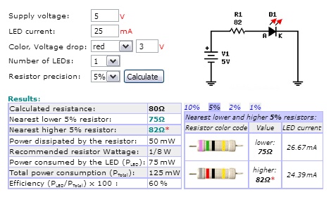
You should drive them separately, each with their own 82Ω resistor.
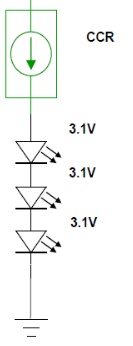
When the supply voltage is very close to the Vf, you can use an LDO constant current regulator (CCR). It acts as an adjustable resistance. It will dynamically change it's resistance to regulate the current.
This is a 25mA CCR On Semi NSI45025AZ
-
1\$\begingroup\$ You certainly DO NOT always need a limiting resistor to control the current through an LED. Providing your voltage is not high enough to cause too much current at the maximum temperature of operation expected (the lowest Vf), then the circuit would be stable. It is ONLY when the supply voltage is high enough to cause thermal runaway that you need some other control such as an external current limiting resistor. The OP clearly understood at least part of this when mentioning that at about 2.5V each the LEDs did light. \$\endgroup\$ Commented Oct 21, 2018 at 18:55
-
\$\begingroup\$ @JackCreasey so why did the OPs LEDs "burn out"? \$\endgroup\$ Commented Oct 21, 2018 at 18:57
-
\$\begingroup\$ In addition to calculate the series resistor you would draw a load line on the V-I characteristics of the LED which DOES take into account both Vf and current for the device. \$\endgroup\$ Commented Oct 21, 2018 at 18:57
-
2\$\begingroup\$ The LEDs burned out because one of them exceeded it's power rating. The OP should reduce the voltage from the power supply OR put a series current limiting resistor in place. However your answer said you ALWAYS need an external resistor and that is simply not the case. \$\endgroup\$ Commented Oct 21, 2018 at 19:00
-
\$\begingroup\$ Im thinking of the best opinion to light both led from the 5v (1.5amp) supply. Do you think it would be better to parallal connect each led using 100 resistor for each LED? \$\endgroup\$ Commented Oct 21, 2018 at 19:04
Nobody makes a "3V" LED but some manufacturers say some of their LEDs are 3V. Some of their "3V" LEDs are actually 2.2V and others are 3.8V so the average of all of them is 3V. If you connect two 2.2V LEDs in series to a 5V power supply then their current will be much too high for them and they will quickly burn out. You need a series current-limiting resistor and a supply voltage high enough so that all three parts in series are bright enough but not too bright.


