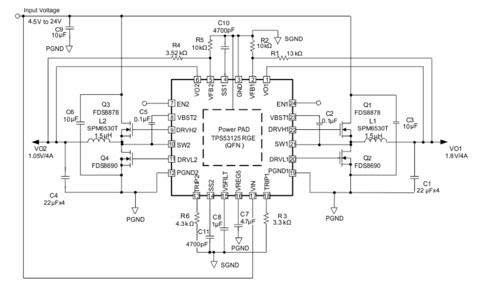
Im trying to play around with some buck converters and have found one that I might want to make a circuit with. The IC I want to use is the the TPS53125 in QFN package. It's a dual output buck converter IC which takes between 4.5 V and 24 V.
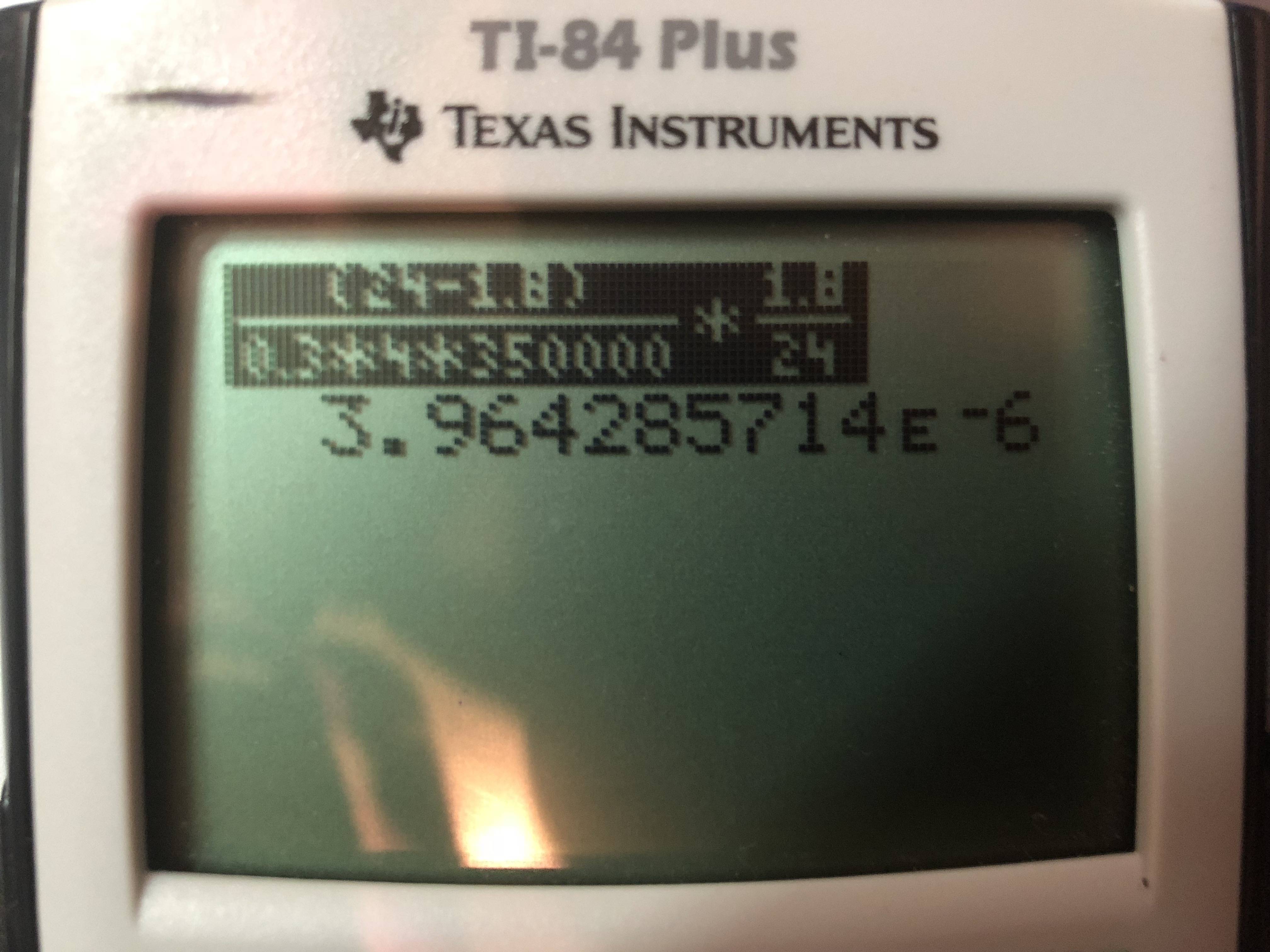
When I use equation 3 from the datasheet to find the suggested inductor value for regulating 1.8 V with a max input of 24V and a output correct of 4 A I end up with the value of 4 uH for the inductor.
Working:
4uH is somewhere in the range that I would expect and sounds correct.
My problem is that in the example circuit above they use a 1.5 uH inductor although they try to regulate 1.8 V at a max of 4 A which should use a 4 uH inductor if you follow equation 3, but instead they use 1.5 uH:
So now I'm very unsure who is wrong? Is the diagram using an inductor value which doesn't conform to the equation or is my calculation faulty?


350-kHz Switching Frequencyim not sure it that's the same asoperating frequencybut I would guess so. And for the second part of your question,- right aboveEquation 3it states that:The inductance value is selected to provide approximately 30% peak to peak ripple current at maximum load.but that ripple current shouldn't affect my math since I used the far right equation in they supplied wich includes it in the ripple current by multiplying the maximum output current by 0.3 as such: "0.3xIo1" \$\endgroup\$